English 960H Digital Video Recorder 8/9-channel models EN INSTRUCTION MANUAL 1
Before You Begin FCC Verification DEFAULT PASSWORD INFORMATION Note: This equipment has been tested and found to comply with the limits for Class B digital device, pursuant to part 15 of the FCC Rules. These limits are designed to provide reasonable protection against harmful interference in a residential installation.
Contents System: General 46 Introduction Getting Started 5 Installation Guidelines 6 DVR Front Panel 6 DVR Rear Panel 7 Connection Diagram 8 Connecting Additional Devices 9 Basic Setup System: User 47 System: System Information 48 System: Maintenance 49 Reference SwannView Link Windows Interface 51 SwannView Link: Local Settings 52 SwannView Link: Device Settings 53 SwannView Link Mobile Interface 57 Controlling the DVR 11 Troubleshooting
Chapter 1 Introduction 4
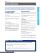
EN INTRODUCTION Getting Started Congratulations on your purchase of this Swann DVR. You’ve made a fine choice for keeping a watchful eye over your home or business. Let’s take a moment to talk about some of the features this DVR offers, and how to get the most out of them. Yes, but you won’t have to read all of it - you should be up and running by page 20! It can take a few hours to connect everything and run through the setup procedure.
EN INTRODUCTION Installation Guidelines • Do not expose the DVR to moisture. Water is the archenemy of electrical components and also poses a high risk of electric shock. • Avoid dusty locations. Dust has a tendency to build up inside the DVR case, leading to a high risk of failure or even fire. • will void your warranty, as well as pose a great risk of fire or electrical shock. INTRODUCTION • Do not expose the DVR to sudden bumps or shocks (for example, being dropped).
EN INTRODUCTION 1 2 3 Name 4 5 6 7 8 9 10 INTRODUCTION DVR Rear Panel Function 1 Power Input This is where you connect the supplied DC 12V power adapter to your DVR. 2 PTZ For connecting RS485 cables to control a PTZ (pan, tilt, zoom) device on the DVR. 3 AUDIO OUT RCA port for audio output. Used to connect your speaker or headphone. 4 USB For connecting the USB mouse. 5 HDMI The primary video output of the DVR.
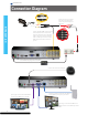
EN INTRODUCTION Connection Diagram Connect the cameras to power using the power splitter then connect the power adapter to a wall outlet. INTRODUCTION Connect the Video (BNC-connector) and Power cables from the camera to the extension cable then connect the Video cable on the other end of the extension cable to a Video input on the rear of the DVR. Do this for the other cameras in your kit. Connect the power supply to the Power input on the DVR and then plug it into a wall outlet.
EN INTRODUCTION Connecting Additional Devices An external hard drive with an eSATA port can be connected to the eSATA port on the DVR. The Audio In ports can be used to connect audio devices such as microphones to the DVR. INTRODUCTION The Audio Out port can be used to connect a pair of speakers or headphones. It can be used to record live footage in the same way as the interal HDD(s). The PTZ port (RS485) can be used to connect compatible PTZ devices, such as this Swann PTZ dome.
Chapter 2 Basic Setup 10
EN BASIC SETUP Controlling the DVR Starting the DVR for the first time: When you first boot the DVR, it will automatically start the Setup Wizard which will guide you through the various setup options available. The USB Mouse The easiest way to operate the DVR is to use the included USB optical mouse - we put together the look and feel of the menu system specifically for mouse-friendly navigation. The controls are pretty easy to remember - heck, there are only two buttons. It couldn’t be simpler.
EN BASIC SETUP Setup Wizard: General The Setup Wizard will run automatically the first time you start the DVR.
EN BASIC SETUP Setup Wizard: Email Email If you want the DVR to send email alerts as alarm events are detected, then you’ll need to configure an outgoing email server for the DVR to use, and choose an email address for it to send to. We recommend creating an account with Gmail (www.gmail.com) specifically for the DVR. These instructions assume you’re using a GMail account. If you’re using a different email, see “Network: Advanced: Email Settings” on page 36 for details. Enable SSL or TLS: Enable.
EN BASIC SETUP Setup Wizard: System Time NTP NTP stands for “Network Time Protocol”. It’s a way for the DVR to connect to the Internet and automatically update and maintain accurate time. There’s no requirement to use NTP, but it’s easy to setup and free to use, so there’s really no reason not to. BASIC SETUP NTP Server: The default server used to obtain accurate time. NTP Port: The default is 123.
EN BASIC SETUP Setup Wizard: Account Configuration Account Configuration Here you can change the default password of the Admin account. For on-going protection against unauthorized access, we strongly suggest setting a new password for your Admin account. User Name: The DVR’s default administration account, which is always called “Admin”. You can’t change the Admin user name. Password: The password you’d like to be associated with the Admin account.
EN BASIC SETUP Setting up your Smartphone or Tablet Have a Smartphone or Tablet? Then head to the respective Apple App Store or Google Play, download the SwannView Link app (or SwannView Link HD for tablets) for free and turn your iOS or Android device into a monitoring centre for your DVR. Have the peace of mind that you can monitor your home at any time from any place.
EN BASIC SETUP Setting up your PC SwannView Link Software Your DVR comes with powerful remote access and interface software, called SwannView Link. You can setup and configure almost all aspects of the DVR from the SwannView Link interface. The SwannView Link software will allow you to: • view images from your DVR in real-time, • playback recorded footage, • copy footage to your local PC and • adjust settings and configure the DVR.
EN BASIC SETUP Setting up your PC Logging on to SwannView Link • To connect from your PC to your DVR, make sure your DVR is on and all connections are ok. • On your PC, open the email that your DVR sent when you were setting up your email account during the Setup Wizard which should look something like this image and locate the the UID: • Copy the UID (highlight the text - right click with your mouse and click “Copy”).
EN BASIC SETUP Live View Mode The Live View Screen Live View is the default display mode for the DVR. Each camera that’s connected to the DVR will be displayed here. You can check the status and operate your DVR and cameras with the icons and menus on the Live View screen. BASIC SETUP Status Icons Menu Bar Status Icons Information on the DVR and camera status is displayed as icons on the Live View screen. Each camera will show its own status icons.
EN BASIC SETUP Live View Mode Menu Bar To open, right click with the mouse on the Live View screen. Opens the main menu. Runs the initial startup wizard. A B C D E F G H I J K L A Single Camera View: Shows images from one camera in full-screen. B Four-Camera (2 x 2) View: Divides the screen into four viewing windows. C Eight-Camera (1+7) View: Divides the screen into eight viewing windows - one large and seven small windows.
EN BASIC SETUP Menu Layout Camera Display Output Encode Recording Option Schedule Playback Search Backup Event / Log General Network Email Settings Advanced NTP Status IP Filter Menu Bar Motion BASIC SETUP DDNS Alarm Video Loss Exceptions HDD Device S.M.A.R.
Chapter 3 Menu Functions 22
EN MENU FUNCTIONS Overview This chapter consists of a guide to performing common and advanced functions through the menus in the DVR system; a How To... guide. We recommend that you read the previous chapter, Chapter 2 - Basic Setup, complete the Setup Wizard to get your DVR up and working and become familiar with operating the DVR in Live View mode before continuing with this chapter. By Default...
EN MENU FUNCTIONS Display: Camera The Display: Camera menu is where you can make adjustments to how the DVR displays the feed coming from your cameras. You can adjust aspects of each channel/ camera, such as: • the camera’s name • what information will be displayed onscreen, and where this information will be displayed • whether information such as the date will be recorded directly onto your videos • any areas of the video you want “masked” - that is, left blank Camera No.
EN MENU FUNCTIONS Display: Output The Display: Output menu is where you can control how the DVR is going to deliver an image to your television, screen or monitor.
EN MENU FUNCTIONS Recording: Encode The Recording: Encode menu allows you to alter and customize how the DVR records footage and “encodes” the files. “Encoding” is a term which refers to the compression algorithm (a fancy computer term for “make the file smaller while retaining visual quality”) used by the DVR. You can choose and alter: Camera No.: The camera feed you want to alter the settings for. These are numbered sequentially, and correspond to the BNC video inputs labelled on the rear of the DVR.
EN MENU FUNCTIONS Recording: Option The Recording: Option menu lets you change some aspects of how the DVR will record footage, such as: • whether the DVR will record a short video before events take place, • how long after events take place the DVR will continue to record for, • how the DVR will store and divide long recordings into “packs” and • whether the DVR will record over old footage to make room for new events.
EN MENU FUNCTIONS Recording: Schedule This example image shows a recording schedule defined for a channel with the DVR’s recording modes. If the DVR was started with this shedule, the selected channel (in this case Channel 1) would: Time • Not record anything from midnight (00:00) to 6am (06:00). • Record based on Motion from 6am (06:00) until 6pm (18:00). • Record constantly from 6pm (18:00) until midnight (00:00).
EN MENU FUNCTIONS Search: Playback • Select the channel you’d like to playback. Note: The DVR can playback up to 4 channels at a time (8-ch models) or one channel only (9-ch models). Displaying multiple video feeds simultaneously may cause a reduction in playback framerate from realtime to near-realtime. • From the Video Type menu, select the type(s) of video you’d like to playback. The options are Manual, Schedule, Motion and All. • Set your Start Date/Time and your End Date/Time.
EN MENU FUNCTIONS The Playback Interface MENU FUNCTIONS The Playback interface is quite similar to a computer’s media player, or to the on-screen display of a DVD/Blu-ray player. Most of the controls are quite straight forward, and operate in the same way as a standard media player. Current Position: A basic progress meter. You can click to move the current position icon to quickly scan through video events. Volume Control: Alters the output volume of playback.
EN MENU FUNCTIONS Specific Incident Backup Cut Copy Say you’ve got an hour of video recorded as a single pack, and the interesting bit is from 33:12 to 33:26. We’re sure you don’t want to copy and convert the whole hour for those precious 14 seconds. So, there is a better way! Shown above is the Playback Control Interface, explained in more detail in the previous page (see “The Playback Interface” on page 30).
EN MENU FUNCTIONS Search: Backup While the backup process is executed, the DVR will display a pair of progress meters. The top one indicates the progress of the current video event, the lower one shows the overall progress. To end the backup process before it’s complete, choose Cancel. Some or all of the incidents you selected will not have been copied. While backing up, particularly when transcoding to AVI, the DVR might take a few moments to register that you’ve selected Cancel.
EN MENU FUNCTIONS Network: General DHCP: DHCP (Dynamic Host Configuration Protocol) is a system where one device on your network (usually a router) will automatically assign IP addresses to devices connected to the network. STATIC: Static networks require all devices to have their IP addresses manually defined, as there is no device dedicated to automatically assigning addresses. PPPoE: An advanced protocol that allows the DVR to be more directly connected via a DSL modem.
EN MENU FUNCTIONS Network: Advanced Note: Many of the following networking settings are not required when using SwannLink P2P for remote access. MENU FUNCTIONS DDNS: The place to configure the DVR to automatically update a dynamic DNS service. DDNS is not required for SwannLink P2P remote access. If you intend to access your DVR using older IP technology you will need to configure this service. See “Network: Advanced: DDNS” on page 35 for details on setting up and configuring the DDNS.
EN MENU FUNCTIONS Network: Advanced: DDNS Static and Dynamic IP Addresses In much the same way as your home network can use static or dynamic IP addresses, many Internet providers don’t issue (or charge more for) a static IP address for users. The easiest way to find out is to contact your Internet service provider. Alternately, you can access the www.whatismyip.com service, make a note of your IP, then reboot your router/ gateway. This should refresh your Internet connection.
EN MENU FUNCTIONS Network: Advanced: Email Settings If you want the DVR to occasionally drop you a line, share news, tell you about its day and - more importantly - tell you what’s going on around your home or business as it happens, then you can configure it to automatically send email alerts as events happen. We suggest using Gmail as your email client - it’s quite easy to set up an account and use it solely for the DVR. We’ve tested the email procedure with Gmail, and it does work.
EN MENU FUNCTIONS Network: Advanced: IP Filter The IP Filter can be used to modify which IP addresses have permission to talk to the DVR and which do not. This is an advanced feature, and is recommended for advanced users only. Tinkering with things here - if you’re not sure what you’re doing - is more likely to break things than make anything better. MENU FUNCTIONS Network: Network Status The Network Status screen displays a quick summary of your network settings.
EN MENU FUNCTIONS Alarm: Motion If you’re planning to use Motion Detection as the primary (or sole) recording mode for the DVR, it’s worth taking a moment to ensure it’s properly configured. If the motion detection sensitivity is too sensitive, then the DVR will record too frequently or continually - any benefit of motion detection will be lost. If the motion detection sensitivity is not sensitive enough, then the DVR will not record when it should and may not record anything at all.
EN MENU FUNCTIONS Alarm: Motion Detection Configuration To set the Motion Detection Area Sensitivity: The Sensitivity setting is controlled by a slider, allowing you to set a value between 0 and 50. The lower the number, the more sensitive the motion detection will be. There are four time periods which you can define different motion sensitivity values for. You can change what time(s) each period starts and ends to best match the changing lighting conditions in your location.
EN MENU FUNCTIONS Alarm: Motion Detection Notes Motion Detection Recording Setup PTZ systems are fundamentally incompatible with motion detection. Avoid enabling motion detection on a channel which has a PTZ system attached to it - especially when the PTZ system is set to Cruise Mode. but we’re continually surprised by stories from our users) it is important to have as much information as possible.
EN MENU FUNCTIONS Alarm: Motion Detection - Action Audio Warning: The DVR will use its internal buzzer to emit an alarm tone. It sounds like an old computer indicating an error, or a large truck backing up. Send Email: The DVR will send an auto-email alert when the event type you’ve selected occurs. The Email Settings button will take you to the same email configuration screen accessible from the Network menu - see “Network: Advanced: Email Settings” on page 36 for details.
EN MENU FUNCTIONS Alarm: Exception An Exception is any deviation from the DVR’s normal behaviour - phrased another way, it’s like saying the DVR’s been working fine except for these events Exception Type: What event type you’d like the DVR to react to. By configuring the Action for these events, you can create any combination of audio alerts (see below) or auto-emails to be sent for different event types.
EN MENU FUNCTIONS Device: HDD Typically, there will be one entry here, and it will be the hard drive that came with the DVR - you’ll get many years of usage out of the included hard drive. The drive connected to the internal SATA port will be listed here. A drive connected via eSATA will appear on this list, and be useable in the same manner as an internal HDD.
EN MENU FUNCTIONS Device: PTZ Important: Don’t use Motion Detection on channels with PTZ cameras attached. The DVR can’t tell the difference between something moving in front of the camera and the camera itself moving! PTZ Settings Accessing the PTZ Controls This is where you can configure the DVR to be able to operate PTZ devices. PTZ stands for Pan, Tilt & Zoom. The PTZ controls can be accessed from the Live Viewing screen by choosing the PTZ icon on the menu bar.
EN MENU FUNCTIONS Device: PTZ PTZ Control Window PTZ Context Menu Arrows: Moves the camera in the direction selected. Camera No: Switch quickly between cameras. Speed: How fast the camera will move. The higher the number, the faster the movement. Note that the actual speed of movement will depend upon the capabilities of your particular PTZ device. Call Preset: Returns the camera to a Preset point. Focus: Alters the focal point of a PTZ device with a varifocal lens.
EN MENU FUNCTIONS System: General The System: General menu contains many of the settings you’ll need to configure to get the most out of your DVR system. Most importantly: • The time and date can be set here. • You can select the language you want for the menus/GUI. • The configuration for automatic adjustment to daylight savings time is here. • You can easily enable or disable password protection - but will have to create a valid username/password.
EN MENU FUNCTIONS System: User The System: User menu is where you can define and configure the different levels of access various users have to the DVR. We suggest that at minimum the admin account be password protected, as it has access to all aspects of the DVR’s operation. To add additional users, choose Add. To remove a user, choose Delete. To customize a user’s level of access, choose Modify. You cannot modify the access level of the default admin account - they can do everything.
EN MENU FUNCTIONS System: System Information If you’re looking at the System Information screen, you’ve probably been directed to do so by Swann Technical Support. If we haven’t told you to come here, you might be wondering what all the information means. On a day-to-day level, the answer is “very little”. However, if you’re still curious: Device Name: The name that the DVR considers to be its own and what it will use to register an IP address with your DHCP host.
EN MENU FUNCTIONS System: Maintenance To maintain the operational integrity of the DVR, it is suggested that it be rebooted periodically. In much the same way that a computer can become unstable if left on for an extremely long time, the DVR can become unstable. It is strongly suggested that the DVR be rebooted at least once per week. However, as this can be a hassle (particularly if the DVR is stashed away somewhere inconvenient) you can set the DVR up to reboot itself.
Chapter 4 Reference 50
EN REFERENCE SwannView Link Windows Interface Preview / Playback / Setup Image Controls Channel List Main Viewing Area Playback and Backup Links Viewing Modes & Volume Control 1 2 3 4 5 6 7 8 9 1. Start Live View 2. Stop Live View 3. Snapshot 4. Video Capture 5. Previous Page 6. Next Page 9. Full Screen 7. Volume 8. Split-Screen Preview: The default live-view screen of SwannView Link.
EN REFERENCE SwannView Link: Local Settings The local configuration screen is where you can customise how SwannView Link will store and process footage on the local PC when you download it from the DVR. About transcoding to AVI: Record Path: Where SwannView Link will save recordings if you select Record from the Preview screen. Transcoding, while a straight-forward process, is very processor intensive. You may notice significant slow-down on your computer while the transcoding takes place.
EN REFERENCE SwannView Link: Device Settings Display: Channel Settings Channel Name (Check Box): Whether the channel’s name will be displayed on screen or not. Channel Name: The title you’d like to give that camera. Record Data: Whether the overlays (Channel Name, Date and so on) will be recorded onto the video with your images. Position Settings: Select the position of the channel name and record date labels that are overlaid on the screen. Mask (Check Box): Turns the masking function on or off.
EN REFERENCE SwannView Link: Device Settings Network: General Be careful adjusting settings here - if the DVR can’t access the network anymore, you won’t be able to configure it remotely! Network Access: How your network is addressed - either DHCP or STATIC IP addressing. Subnet Mask: A required additional piece of IP addressing information. Gateway: The way “out” of your network, to the Internet. Auto DNS / Static DNS: Whether the DVR will automatically select a DNS server, or use one you assign.
EN REFERENCE SwannView Link: Device Settings Alarm: Motion Detection Channel: The channel you’re configuring the motion detection settings for. Enable: Whether the motion detection is enabled for the channel currently selected. Sensitivity: A sliding scale between 1 and 50. The number refers to the number of pixels (as a percentage) that have to “change” between frames - okay, this one is a little more complex than this summary will allow.
EN REFERENCE SwannView Link: Device Settings Device: HDD Operates in the same way as the HDD management menu in the DVR menu. Rather than attempt to summarize here, it’s easier to simply turn to page 43 to learn more. System: General / System Information / Maintenance Operates in the same way as the System submenus in the DVR menu. Rather than attempt to summarize here, it’s easier to simply turn to page 46 to learn more.
EN REFERENCE 1. Menu - Opens the menu to allow you to select the various different menu screens. 2. Live View - The Live View screen. A red border will surround the currently selected camera. 3. Group Indicator - SwannView Link can display up to 4 channels at a time. The white dot shows which group of 4 cameras you are currently viewing. Swipe left or right to change between groups of cameras. 4. Snapshot - Takes a snapshot of the currently selected camera and saves it to your mobile device. 5.
EN REFERENCE SwannView Link Mobile Interface REFERENCE 58 1. Live - Takes you back to the Live View screen from any other screen. 2. Record List - Takes you to the Record List page where you can playback video that you have previously recorded to your mobile device. 3. Device - The Device Management screen where you can add, edit or remove your DVR. 4. Help & About Us - Tap this to access the built-in manual as well as the version information.
EN REFERENCE Troubleshooting Q: The images from my cameras are black & white and/or flickering. What’s up? sensitive at night (whenever the active infrared night vision is active). A: Most likely, your Video Standard isn’t set correctly for your region. Check out the section on PAL/NTSC (“System: General” on page 46) for more information. As a rule of thumb, set your video standard to NTSC if you’re in the USA or Canada, or PAL if you’re in Europe, the UK or Australia. 3.
EN REFERENCE Third Party Hardware Due to it’s nature as a networked device, the DVR is often required to operate with third party hardware. We do everything we can to ensure the DVR is compatible with as many third party devices as possible, there will always be some that require a little extra configuration. Routers I’m using a router which doesn’t support DHCP addressing or Some devices on my network require STATIC addressing. You’ll need to set the address of the DVR manually.
EN REFERENCE Warranty Information USA Swann Communications USA Inc. 12636 Clark Street Santa Fe Springs CA 90670 USA Australia Swann Communications Unit 13, 331 Ingles Street, Port Melbourne Vic 3207 Australia United Kingdom Swann Communications LTD. Stag Gates House 63/64 The Avenue SO171XS United Kingdom Warranty Terms & Conditions Swann Communications warrants this product against defects in workmanship and material for a period of one (1) year from its original purchase date.
English Helpdesk / Technical Support Details Swann Technical Support All Countries E-mail: tech@swann.