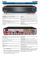
English English 4 / 8 Channel D1 Realtime H.
English Before You Begin FCC Verification NOTE: This equipment has been tested and found to comply with the limits for Class B digital device, pursuant to part 15 of the FCC Rules. These limits are designed to provide reasonable protection against harmful interference in a residential installation.
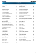
English Contents Before You Begin 2 The Playback Interface Contents 3 Network: General 29 Introduction 4 Network: Advanced 30 Basic DVR Operation 4 Network: Advanced: DDNS 31 Layout of the DVR 5 Network: Advanced: NTP 31 Connection Diagram 6 Network: Advanced: IP Filter 32 Connecting Additional Devices 7 Network: Network Status 32 Installation Guidelines 8 Network: Advanced: Email Settings 33 Layout of Remote Control 8
English Introduction Congratuations on your purchase of this Swann DVR. You’ve made a fine choice for keeping a watchful eye over your home or business. Let’s take a moment to talk about some of the features this DVR offers, and how to get the most out of them. Multi-Channel Recording Solution The DVR records 4 or 8 channels (depending on your model) at “D1” resolution. What’s this “D1”? D1 is a (slightly inaccurate) term for a certain resolution of video which is now often called “broadcast quality”.
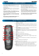
English Layout of the DVR 8 9 6 1 7 2 3 4 5 1) USB 2.0 Port: For connecting USB external storage to the DVR for backup, or for applying new firmware. 5) Select: As the name suggests, it selects an option or item from a menu. 2) Play/Pause: Opens the playback interface from the live viewing mode. Pauses playback or resumes playback from paused. 6) D-pad: For navigating around menus when you’re not using the mouse. (Why aren’t you using the mouse? It’s awesome.
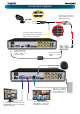
English Connection Diagram Connect your cameras to power, using the a powersplitter (if included). Connect the BNC outputs from your cameras into the yellow BNC inputs on the rear of the DVR. Connect the DC12V Output from the power supply to the power input. Connect the power supply to a wall outlet. Connect the mouse to the USB2.0 port. Connect an ethernet cable from the LAN port on the DVR to a spare port on your router.
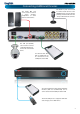
English Connecting Additional Devices The Audio In ports can be used to connect audio devices to the DVR. Obviously, your microphone probably won’t look like that one - they’re often built into cameras. The Audio Out port can be used to connect a stereo, speakers, headphones or other external sound device. The PTZ port (RS485) can be used to connect compatible PTZ devices, such as this Swann PTZ dome. An external hard drive with an eSATA port can be connected to the eSATA port on the DVR.
English Installation Guidelines • Do not expose the DVR to moisture. Water is the archenemy of electrical components and also poses a high risk of electric shock. • Avoid dusty locations. Dust has a tendency to build up inside the DVR case, leading to a high risk of failure or even fire. • Only install the DVR in a well ventilated space. Like all electronics, the circuitry and hard drive in the DVR produce heat, and this heat needs a way out.
English Installing MyDVR on PC Your DVR comes with powerful remote access and interface software, called MyDVR. You can setup and configure almost all aspects of the DVR from the MyDVR interface. The MyDVR software will allow you to: • view images from your DVR in real-time, • playback recorded footage, • copy footage to your local PC and • adjust settings and configure the DVR.
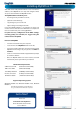
English MyDVR: Logging In If you’re logging in to the DVR for the first time via a local network, then use the following settings: Before running MyDVR for the first time: Ensure your DVR is connected to a network and (if accessing via the Internet) you know the Public IP Address of the DVR or the DDNS address (see “Network: Advanced: DDNS” on “Network: Advanced: DDNS” on page 31 for more).
English MyDVR: Interface Preview / Playback / Setup PTZ Controls & Image Controls Channel List Main Viewing Area Playback and Backup Links Viewing Modes & Volume Control Preview: The default splash screen of MyDVR. The screen layout emulates the multi-channel live view screen of the DVR, showing you images coming directly from your cameras in near-realtime (some delay is caused by the network/Internet connection you’re using to access the DVR).
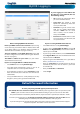
English MyDVR: Local Configuration The local configuration screen is where you can customise how MyDVR will store and process footage on the local PC when you download it from the DVR. Record Path: Where MyDVR will save recordings if you select Record from the Preview screen. Download Path: Where MyDVR will save footage that you’ve downloaded from the DVR. Snapshot Path: Where MyDVR will save still images captured using the snapshot function.
English MyDVR: Configuration Overview Display: Camera (see page 20) Channel Name (Check Box): Whether the channel’s name will be displayed on screen or not. Channel Name: The title you’d like to give that camera. Record Data: Whether the overlays (Channel Name, Date and so on) will be recorded onto the video with your images. Mask (Check Box): Turns the masking function on or off. Mask (Setup): Creates a black privacy overlay which masks part of your images. Will affect recordings.
English Network: General (see page 29 for more) Be careful adjusting settings here - if the DVR can’t access the network anymore, you won’t be able to configure it remotely! Network Access: How your network is addressed - either DHCP or STATIC IP addressing. Subnet Mask: A required additional piece of IP addressing information. Gateway: The way “out” of your network, to the Internet. Auto DNS / Static DNS: Whether the DVR will automatically select a DNS server, or use one you assign.
English Alarm: Motion Detection (see page 34) Channel: The channel you’re configuring the motion detection settings for. Enable: Whether the motion detection is enabled for the channel currently selected. Sensitivity: A sliding scale between 1 and 50. The number refers to the number of pixels (as a percentage) that have to “change” between frames - okay, this one is a little more complex than this summary will allow.
English Device: PTZ (see page 40) Channel: The channel you’d like to configure a PTZ camera for. Settings: See page 40 for more information about the PTZ settings you’ll find here. You’ll probably need the documentation that came with your PTZ camera to figure out how to fill out this configuration page. System: General (see page 41) System Standard: Lets you change the DVR between PAL or NTSC standards. NTSC operates at 30 frames per second, and has an effective resolution of 720 x 480.
English Remote Access From a Mobile Device Using the SwannView app for mobile devices, you’ll be able to log into your DVR from almost anywhere you can imagine (or, at least, get a decent signal - like everyone, we’re at the mercy of your phone company!) and view images coming from your cameras in real-time (or as close to as wireless networking will permit). How cool is that? We’re pretty sure this was science-fiction just a few short years ago. You’ll need a compatible mobile device.
English Operating the DVR Locally The camera icon indicates that this camera is currently recording. This icon will be the same whether the recording was scheduled, initiated manually or triggered by motion (though the motion icon will also be present if there’s motion detected). The motion icon indicates that the DVR has detected motion coming from this camera. It doesn’t necessarily mean it’s recording (the camera icon will be there, too, if that’s the case!).
English Menu Layout Camera Display Output Encode Recording Option Schedule Playback Search Backup Event / Log DDNS General Network Email Settings Advanced NTP Status IP Filter Menu Bar Motion Alarm Video Loss Exceptions HDD Device S.M.A.R.
English Camera: Display The Display: Camera menu is where you can make adjustments to how the DVR displays the feed coming from your cameras. You can adjust aspects of each channel/ camera, such as: Camera No.: Choose the camera / channel you want to edit here. The Camera No is the same thing as the number written on the rear panel next to the BNC socket used to connect the camera. Camera Name: Select a name for the camera you’ve selected. By default, all channels are named as the Camera No.
English Camera: Output The Camera: Output menu is where you can control how the DVR is going to deliver an image to your television, screen or monitor. You’ll be able to adjust such items as: Resolution: The number of “little dots” that make up an image. This should be set as high as possible, but equal to or lower than the maximum resolution your screen/monitor can display. Things change a little depending on what kind of monitor you’re using, and how it’s connected.
English Recording: Encode The Recording: Encode menu allows to alter and customize how the DVR records footage and “encodes” the files. “Encoding” is a term which refers to the compression algorithm (a fancy, computer term for “make the file smaller while retaining visual quality”) used by the DVR. You can choose and alter: Camera No.: The camera feed you want to alter the settings for. These will be numbered sequentially, and correspond to the BNC video inputs labelled on the rear of the DVR.
English Recording: Option The Recording: Option menu lets you change some aspects of how the DVR will record footage, such as: • whether the DVR will record a short video before events take place, • how long after events take place the DVR will continue to record for, • how the DVR will store and divide long recordings into “packs” and • whether the DVR will record over old footage to make room for new events.
English Recording: Schedule Important Guidelines The schedule presented on-screen applies to one channel on one specific day of the week only. Use the Copy To functions to quickly assign identical schedule layouts to multiple days/channels at once. Be careful when programming your schedule. It’s one of the most important aspects of setting up your DVR, and if it’s wrong in any way, it could lead to disastrous complications later. Copy To: There are two Copy To buttons on the Schedule Menu screen.
English Search: Playback To initiate playback: • Select the channels you’d like to playback. Note that the DVR can only playback a limited number of channels simultaneously: the DVR cam playback 2 channels at realtime, and up to four channels at nearrealtime. • From the Video Type menu, select the type(s) of video you’d like to playback. The options are Manual, Schedule, Motion and All. • Set your Start Date/Time and your End Date/Time. • Select Search.
English Search: Backup To backup footage: • Connect a USB flash drive or a USB HDD to the USB port on the front of the DVR - OR - • Connect an eSATA HDD to the eSATA port on the rear of the DVR. • Choose the camera(s) you want to backup footage from. • From the Video Type menu, select the type(s) of video you want to backup. The options are Manual, Motion and Schedule - or All if you want everything. • Set your Start Time and End Time. • Select Backup.
English Search: Event The Event Search menu will show you recordings that were triggered by the DVR detecting motion. Typically, the majority of recordings based upon “Events” are likely to be recordings triggered by the DVR’s motion detection feature. The search function operates in the same way as the main playback search: the only difference is you’ll select an Event Type rather than a Video Type.
English The Playback Interface The Playback interface is quite similar to a computer’s media player, or to the on-screen display of a DVD/Blu-Ray player. Hide Console: Maximizes the area onscreen for playing back your footage by hiding the on-screen controls. Most of the controls are quite straight forward, and operate in the same way as a standard media player’s. Exit Playback: Leaves the playback interface and returns to the live viewing mode. Current Position: A basic progress meter.
English Network: General Network Access: Here you can choose between the three different types of networks that the DVR can be connected to. The three types of networks are: DHCP: DHCP (Dynamic Host Configuration Protocol) is a system where one device on your network (usually a router) will automatically assign IP addresses to devices connected to the network.
English Network: Advanced DDNS: The place to configure the DVR to automatically update a dynamic DNS service. If you want to remotely access the DVR via the Internet, you’ll probably need to configure a DDNS account. See “Network: Advanced: DDNS” on page 31 for details on setting up and configuring the DDNS. HTTP Port: This is the port through which you will be able to log in to the DVR. • Like the server port, it will need to be forwarded properly in order to ensure smooth, latency-free communication.
English Network: Advanced: DDNS Static and Dynamic IP Addresses In much the same way as your home network can use static or dynamic IP addresses, many Internet providers don’t issue (or charge more for) a static IP address for users. The easiest way to find out is to contact your Internet service provider. Alternately, you can access the www.whatismyip. com service, make a note of your IP, then reboot your router/gateway. This should refresh your Internet connection.
English Network: Advanced: IP Filter The IP Filter can be used to modify which IP addresses have permission to talk to the DVR and which do not. This is an advanced feature, and is recommended for advanced users only. Tinkering with things here - if you’re not sure what you’re doing - is more likely to break things than making anything better. Network: Network Status The Network Status screen shows you a quick summary of your network settings.
English Network: Advanced: Email Settings If you want the DVR to occasionally drop you a line, share news, tell you about its day and - more importantly - tell you what’s going on around your home or business as it happens, then you can configure it to automatically send email alerts as events happen. We suggest using Gmail as your email client - it’s quite easy to set up an account and use it solely for the DVR. We’ve tested the email procedure with Gmail, and it does work.
English Alarm: Motion If you’re planning to use Motion Detection as the primary (or sole) recording mode for the DVR, you must ensure it’s properly configured. If the motion detection sensitivity is too sensitive, then the DVR will record too frequently or continually - any benefit of motion detection will be lost. If the motion detection sensitivity is not sensitive enough, then the DVR will not record when it should and may not record anything at all.
English Alarm: Motion Detection Configuration • Limit the motion sensitive area to only the areas in view that a target could be. In particular, large featureless areas in the camera’s view are the ones most likely to give false triggers - turning off the motion sensitivity to any area a target cannot move infront of will help reduce false triggers. Note: The motion detection feature will seem more sensitive at night, particularly when using low-light or active infrared cameras.
English Alarm: Motion Detection - Action Audio Warning: The DVR will use its internal buzzer to emit an alarm tone. It sounds like an old computer indicating an error, or a large truck backing up. Send Email: The DVR will send an auto-email alert when the event type you’ve selected occurs. The Email Settings button will take you to the same email configuration screen accessible from the Network menu - see “Network: Advanced: Email Settings” on page 33 for details.
English Alarm: Video Loss Alarm: Video Loss Video Loss is regarded as a potential alarm event, and is considered to occur any time that the DVR doesn’t receive an active video signal on any of its inputs. The default behaviour of the DVR, when a channel has no incoming video signal, is simply to display “Video Loss” in white text on a black background over the associated channel. If you’re not using all the inputs on your DVR, then some channels will be in “permanent” Video Loss state.
English Alarm: Exception An Exception is any deviation from the DVR’s normal behaviour - phrased another way, it’s like saying the DVR’s been working fine except for these events Audio Warning: The DVR will use its internal buzzer to emit an alarm tone. It sounds like an old computer indicating an error, or a large truck backing up. Exception Type: What event type you’d like the DVR to react to.
English Device: HDD Here you’ll find a comprehensive list of hard drives connected to the DVR. Typically, there will be one entry here, and it will probably be the hard drive that came with the DVR. This is not a problem, and you’ll probably get years of usage out of the included hard drive. Note that external drives connected by either eSATA or USB will NOT be displayed here. Device: S.M.A.R.T. S.M.A.R.T.
English Device: PTZ Left: The PTZ Settings menu. Above: The PTZ controls, accessed by the PTZ icon on the menu bar. Right: The PTZ context menu. Accessed by right-clicking while the PTZ controls are open. Below: The Menu Bar, with the PTZ icon highlighted in red. PTZ Settings This is where you can configure the DVR to be able to operate PTZ devices. PTZ stands for Pan, Tilt & Zoom. The DVR is compatible with many - but not all - PTZ devices available.
English System: General The System: General menu contains many of the settings you’ll need to configure to get the most out of your DVR system. Most importantly: Language: The language that the DVR’s menus, alerts and other communications will use. This usually defaults to English. Be careful not to change this setting unintentionally - it might be tricky to find the setting to change it back when the DVR is speaking another language! Video Standard: Here you can choose between PAL and NTSC.
English System: User The System: User menu is where you can define and configure the different levels of access various users have to the DVR. We suggest that at minimum the admin account be password protected, as it has access to all aspects of the DVR’s operation. To add additional users, choose Add. To remove a user, choose Delete. To customize a user’s level of access, choose Modify. You cannot modify the access level of the default admin account - they can do everything.
English System: System Information If you’re looking at the System Information screen, you’ve probably been directed to do so by Swann Technical Support. If we haven’t told you to come here, you might be wondering what all the information means. On a day-to-day level, the answer is “very little”. However, if you’re still curious: Device Name: The name that the DVR considers to be its own, and what it will use to register an IP address with your DHCP host.
English System: Maintenance To maintain the operational integrity of the DVR, it is suggested that it be rebooted periodically. In much the same way that a computer can become unstable if left on for an extremely long time, the DVR can become unstable. It is strongly suggested that the DVR be rebooted at least once per month. However, as this can be a hassle (particularly if the DVR is stashed away somewhere inconvenient) you can set the DVR up to reboot itself.
English Troubleshooting Q: The images from my cameras are black & white and/or flickering. What’s up? A: Most likely, your Video Standard isn’t set correctly for your region. Check out the section on PAL/NTSC (“System: General” on page 41) for more information. As a rule of thumb, set your video standard to NTSC if you’re in the USA or Canada, or PAL if you’re in Europe, the UK or Australia.
English Technical Specifications Video Compression Video System Operating System Video Input/Output 4ch Model Input/Output 8ch Model BNC: 4-ch inputs / VGA: 1 output / HDMI: 1 output RCA :4-ch inputs / RCA: 1-ch outputs / HDMI with integrated audio BNC: 8-ch inputs / VGA: 1 output / HDMI: 1 output Audio RCA :4-ch inputs / RCA: 1-ch outputs / HDMI with integrated audio VGA / HDMI: 1024 x 768, 1280 x 1024, 1280 x 720, 1920 x 1080 Refresh Rate 60Hz Aspect Ratio 4:3 / 16:9 Record Frame Rate Display Re
English Warranty Information USA Swann Communications USA Inc. 12636 Clark Street Santa Fe Springs CA 90670 USA Australia Swann Communications Unit 13, 331 Ingles Street, Port Melbourne Vic 3207 Australia United Kingdom Swann Communications LTD. Stag Gates House 63/64 The Avenue SO171XS United Kingdom Warranty Terms & Conditions Swann Communications warrants this product against defects in workmanship and material for a period of one (1) year from its original purchase date.
English Helpdesk / Technical Support Details Swann Technical Support All Countries E-mail: tech@swann.