
User manual

1.
2.
3.
4.
5.
6.
HD590 Colour CCD Security Camera
Manual Focus Lens
Adjustable Camera Stand
)
10m (33feet) Cable
12Volt DC Power Adaptor (adaptor design varies depending on country .
Instruction Manual (this document)
Before permanently fixing your camera in the location which you wish to observe, fix it temporarily and
connect the necessary cables and check using your Video Monitor or TV to ensure you have a clear field
of view. Check also that the camera will not be pointing directly into a strong light source (check at
different times of the day to ensure the sun will not interfere with the image) or that there are any other
obstructions. Once this is complete, adjust the camera for focus and check that you have the correct field
of view. Once you are satisfied that the image is appropriate to your requirements, fix the stand to the
location correctly using the appropriate screws, and if necessary wall anchors. After mounting the
Camera Stand in the location the camera will be used, screw the camera to the stand and tighten firmly.
Use the mounting hole in the top of the camera if mounting the camera under a roof, ceiling or similar
surface to make sure that the picture shows correctly on your monitor.
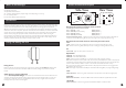
Description of connectors and controls on side of camera
Description of controls and connectors on the back panel of the camera
Lens:
PL:
Dip Switches:
-
Level:
Video Out:
2V DC IN:
Pin arrangement for Auto Iris lens socket
Pin - Video AI DC AI
Pin 2 - Video AI DC AI
Pin 3 - Video AI DC AI
Pin 4 - Video AI DC AI
CS connector locking screw -
Video -
DC -
Power LED -
AWBON-
AWB OFF -
AGC -
EE -
AI -
BLC
Phase Adjustment -
BNC Female connector -
Power connector -
1 (+12V) (DAMP -)
(Not Connected) (DAMP+)
(VIDEO) (DRIVE+)
(GROUND) (DRIVE -)
Tighten this screw to lock the CS connector. Loosen to adjust the CS
connector to assist with focussing the lens if you cannot get a clear image using the focus ring.
Switch to this if using a Video Drive auto iris lens (ignore if using Manual Iris lens)
Switch to this if using a DC (Direct) drive auto iris lens (ignore if using Manual Iris lens)
Lights up when power to camera is on
Auto White Balance ON
Auto White Balance OFF
Auto Gain Control On/Off (On = Low gain control, Off = High gain control)
Electronic Exposure control (
)
Back Light Compensation On/Off (On=Auto BLC, Off=Strong BLC (very bright background))
When using a DC drive Auto Iris lens adjust this control for best image quality
Connects to BNC Male connector as fitted to supplied extension cable
Connect using supplied 12Volt Power Adaptor or extension cable
1
In EE mode, a continuously variable electronic shutter is employed to
automatically control the exposure time of the CCD image sensor according to the incoming light level.
With this mode selected, a fixed or manual iris lens can be used instead of an auto iris lens
In AI mode, the CCD shutter speed is fixed to 1/60(1/50) second. And the incoming light level is
controlled by the auto iris lens.
AWB ON
LENS
EE
BLC ON
VIDEO
AGC ON
DC
OFF
LEVEL
OFF
AI
OFF
PL
12V DC IN
VIDEO OUT
Rear ViewSide View
1
2
3
4
CS connector locking screw
Fitting the lens:
1
Adjust the lens to suit your application:
Focus Adjustment Ring 2
Make sure the CS Connector Locking Screw is tight, then by holding the ( ) carefully screw
the lens into the CS Connector on the front of the camera body making sure you do not cross the
thread.
Turn the ( ) clockwise or anti-clockwise to focus the camera. If the Lens will
not focus, Loosen the
Lens Body
CS Connector Locking Screw and turn the CS Connector either in or out until
correct focus is obtained. Once you have adjusted the focus correctly, re-tighten the CS Connector
Locking Screw firmly, but do not over-tighten.
21
What’s In This Package? Control and Socket Description
Introduction
Fitting and Setting The Lens
2 3