
User's Guide
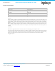
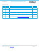
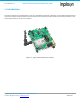
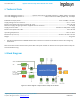
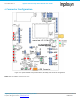
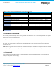
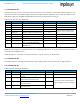
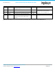
Table Of Contents
- 1. Introduction
- 2. Technical Data
- 3. Block Diagram
- 4. Connector Configuration
- 5. Test Points
- 6. LEDs
- 7. Schematic
- 8. Dimensions
- 9. Integration instructions for host product manufacturers according to KDB 996369 D03 OEM Manual v01
- 9.1. List of applicable FCC / ISED rules
- 9.2. Specific operational use conditions
- 9.3. Limited module procedures
- 9.4. Trace antenna designs
- 9.5. RF exposure considerations
- 9.6. Antennas
- 9.7. Label and compliance information
- 9.8. Information on test modes and additional testing requirements
- 9.9. Additional testing, Part 15 Subpart B disclaimer
- 9.10. Host Product Labelling Requirements
- 10. Disclaimer
- 11. References

NA-20-0386-0006-1.5 Inpixon Swarm Chirp V3 Dev Board User Guide
Inpixon_UG_Swarm_Chirp_V3_Dev_Board_1.5.docx 10
© Inpixon. All rights reserved. | www.inpixon.com FRM0008-A1
Pin No.
Description
Type
Module Pin
Comments
6
DIO_3
Input or Output. Can be used as
interrupt source
25
7
USART_TX
Output: Serial transmission line
12
If connected to a host remove
jumpers on X4. See Figure 4-2
8
USART_RX
Input: Serial receiving line
19
9
TX_ON
Transmitter on (min. on time 50 ms)
26
10
DIV_COEX
Can be used for co-existence
purposes with external BT or Wi-Fi
systems
27
Note: All levels refer to 2.6 V. In any case refer to the Inpixon Swarm Chirp V3 Technical Reference [1]