
User's Guide
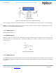
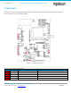
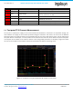
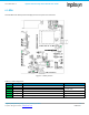
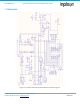
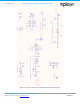
Table Of Contents
- 1. Introduction
- 2. Technical Data
- 3. Block Diagram
- 4. Connector Configuration
- 5. Test Points
- 6. LEDs
- 7. Schematic
- 8. Dimensions
- 9. Integration instructions for host product manufacturers according to KDB 996369 D03 OEM Manual v01
- 9.1. List of applicable FCC / ISED rules
- 9.2. Specific operational use conditions
- 9.3. Limited module procedures
- 9.4. Trace antenna designs
- 9.5. RF exposure considerations
- 9.6. Antennas
- 9.7. Label and compliance information
- 9.8. Information on test modes and additional testing requirements
- 9.9. Additional testing, Part 15 Subpart B disclaimer
- 9.10. Host Product Labelling Requirements
- 10. Disclaimer
- 11. References

NA-20-0386-0006-1.5 Inpixon Swarm Chirp V3 Dev Board User Guide
Inpixon_UG_Swarm_Chirp_V3_Dev_Board_1.5.docx 13
© Inpixon. All rights reserved. | www.inpixon.com FRM0008-A1
Figure 4-3: Jumper matrix with pull-up and pull-down jumper
How to configure each GPIO is explained in detail in the swarm bee API3.0 User Guide [2] sect 5.6.11 and followings.
Note: For a proper debouncing, always connect the jumper as input on X10 first and then change the polarity on X8.
Otherwise, an unpredictable behavior will occur.
4.1.12. Connector X11
Reserved and for future use.
4.1.13. Connector X12
When the jumper is closed, the input voltage of the Inpixon Swarm Chirp V3 module can be measured by the
µController with the corresponding API 3.0 commands GBAT [2]. If a voltage is injected at pin 2 of X3 leave the
connector open.
Figure 4-4: Voltage divider
4.1.14. Connector X13
This jumper bridge when opened allows to connect a current measuring device, like an Ampere meter, in series to
the main power supply of the Inpixon Swarm Chirp V3 module VIN. It measures the sum of all currents consumed by
the module.