System 2TM Modular Media Filters O W N E R’ S M A N U A L E N G L I S H RELE ASE RELE ASE F R A N Ç A I S OU TL ET OU TL ET INSTALLATION, OPERATION & PARTS MODELS PLM100 PLM125 PLM150 PLM300 PLM175 PLM200 This manual should be furnished to the end user of this filter; its use will reduce service calls and chance of injury and will lengthen filter life. Pentair Water Pool and Spa, Inc. © 2010 Pentair Water Pool and Spa, Inc. All rights reserved.
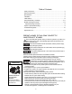
Table of Contents Safety Instructions ...........................................................................................2 General Information.........................................................................................3 Specifications ..................................................................................................4 Installation .......................................................................................................5 Initial Startup.......................
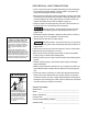
GENERAL INFORMATION • Clean a new pool as well as possible before filling pool and operating filter. Excess dirt and large particles of foreign matter in the system can cause serious damage to the filter and pump. • With a permanent media filter in place and operating correctly, clean water is returned to the pool faster than pool water is being contaminated. A typical pool installation will require approximately one week to obtain and maintain the sparkle that your filter is capable of giving you.
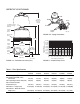
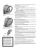
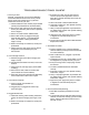
SPECIFICATIONS Filter Inlet RELE ASE Dim B Minimum Service Height Outlet Air Release Valve (Pressure Gauge Behind) To Pool Upper Tank Shell From Pool 4085 1001 FIGURE 1B – Piping Connections Posi-Lok™ Ring Dim A Safety Latch 20 (138) Pressure Drop in Pounds per Square Inch (kPa) Lower Tank Shell 2" NPT Inlet or Drain Drain Plug Pump ET INL 18.58" Dia. (472 mm) Outlet 2" NPT Inlet or Drain 2" NPT 18 (124) 16 (110) 14 (97) 12 (88) 10 (69) 8 (55) 6 (41) 4 (28) 2 (14) 4310 0203 15" Dia.
INSTALLATION Installation of filter should only be done by qualified, licensed personnel. Filter mount must: • Provide weather and freezing protection. • Provide space and lighting for easy access for routine maintenance. (See Figure 1 for space requirements.) • Provide ventilation and drainage for pump. • Be on a reasonably level surface and provide adequate drainage. Piping (See Figure 1B for correct connections): • Piping must conform to local/state plumbing and sanitary codes.
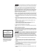
INITIAL START-UP Be sure pump is OFF before starting procedure. Do not operate these filters at more than 50 PSI (345 kPa) under any circumstances! Hazardous pressure. Can cause severe injury or major property damage from tank blow up. Release all pressure and read instructions before working on filter. 1. Securely lock Posi-Lok™ ring in place by rotating ring CLOCKWISE until it “clicks” past the safety latch (see Figure 3). Stop turning as soon as the ring clicks past the latch.
Figure 5 – Insert ring tab in slot in 2152 1195 filter body. NOTICE: Make sure that waste water disposal complies with local codes and ordinances. 4. Remove drain plug and drain all water from tank. 5. Remove Posi-Lok™ ring as follows: a. Press safety latch (below the ring) toward the tank to release it (see Figure 4). b. Hold latch in the release position and rotate ring COUNTERCLOCKWISE to remove. If ring is difficult to turn, tap gently with a rubber mallet to overcome initial resistance.
Risk of chemical burns. Do not attempt to acid clean the filter or module. If the filter requires acid cleaning, have a trained pool professional do the job. NOTICE: When sanitizing your pool using PHMB (polyhexamethylene biquanide based) cleaners, use only PHMB cleaners to clean the module. When using PHMB sanitizers, the filter module MUST be cleaned more thoroughly and frequently than for a pool using chlorine. Follow manufacturer’s instructions carefully.
SYSTEM INSPECTION General: Wash the outside of the filter with a mild detergent and water. Rinse off with a hose. NOTICE: DO NOT use solvents to clean the filter; solvents may damage plastic components in the system. NOTICE: Open the air bleed valve and bleed all air from the filter each time the pump is stopped and restarted. Weekly Inspection: 1. Remove debris from the pool skimmer basket. 2. Stop the pump; open the air release valve to release all pressure. 3.
TROUBLESHOOTING GUIDE 1. Short Cycle Time: C. Excessive air in filter. Vent air from tank and check for pump suction pipe leaks. Clean air bleed filter in module assembly with a hose and soft flow nozzle. NOTICE: CycleTime will vary with each installation and between different areas of the country. The following causes and remedies are for cycle times shorter than normal for your area. A. Chlorine residual too low; maintain proper residual (consult pool professional for recommendation). D.
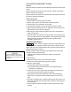
REPAIR PARTS 11 2B 1 3B 10 12 2A Key No. Description 1 2A 2B 10 3A 3B 4 5 6 7 8 9 10 11 12 12 12 12 12 12 13 • • • • • • • • • • • • • • 3A 4 13 5 RELEASE 6 7 OUTLET 8 9 Base rotated 90 to show check valve installed. 4309 0203 • * ** *** 11 Qty.
Blank Page
Système 2TM à matériau filtrant modulaire NOTICE D’UTILISATION E N G L I S H RELE ASE RELE ASE F R A N Ç A I S OU TL ET OU TL ET INSTALLATION, FONCTIONNEMENT ET PIÈCES MODÈLES PLM100 PLM125 PLM150 PLM300 PLM175 PLM200 Cette Notice doit être remise à l’utilisateur de ce filtre; elle permettra de diminuer les appels de service, les possibilités de blessures et elle prolongera la durée du filtre. Pentair Water Pool and Spa, Inc. © Pentair Water Pool and Spa Inc., 2010. Tous droits réservés.
Table des matières Instructions de sécurité .......................................................................................2 Renseignements généraux .................................................................................3 Spécifications ......................................................................................................4 Installation ...........................................................................................................5 Mise en service initiale ......
RENSEIGNEMENTS GÉNÉRAUX • Dans le cas d’une piscine neuve, la nettoyer le mieux possible avant de la remplir et de faire fonctionner le filtre. Le filtre et la pompe risquent d’être endommagés si le système contient trop de saletés et de grosses particules de corps étrangers. • Dans le cas d’un filtre à matériau filtrant permanent en place et fonctionnant bien, l’eau propre retourne plus vite dans la piscine qu’elle peut être contaminée.
SPÉCIFICATIONS Filter Filtre Inlet Admission RELE ASE Dim BB Dimension Minimum Hauteur minimale Service en Height service (le AirPurgeur Released’air Valve manomètre est (Pressure Gauge derrière) Behind) Outlet Sortie Vers le To Pool piscine Upper Moitié supérieure Tank du réservoir Shell EnFrom provenance dePool piscine Bague Posi-Lok™ Posi-LokMD Ring 4085 1001 FIGURE 1B – Les branchements de tuyauterie Dimension Dim A A 20 (138) in Chute dePressure pressionDrop en livres par Pounds per Square
INSTALLATION L’installation du filtre doit être effectuée par du personnel qualifié et compétent. Le support du filtre doit : • pouvoir protéger des intempéries et du gel. • procurer l’espace et l’éclairage suffisants pour procéder facilement à l’entretien périodique (voir la Figure 1 pour les espaces requis). • permettre la ventilation et la vidange de la pompe. • être sur une surface de niveau et assurer un écoulement adéquat.
MISE EN SERVICE INITIALE S’assurer que la pompe est ARRÊTÉE avant de procéder à la mise en service. Pression dangereuse. De graves blessures ou d'importants dommages matériels peuvent être causés si le réservoir éclate. 1. Dissiper toute la pression et lire toutes les instructions avant d'intervenir sur le filtre. 2. 3. 4. 5. 6. Tab Patte Latch Verrou 2149 1195 Figure 3 – Tourner la bague Posi-LokMD jusqu’à ce que la patte se verrouille derrière le verrou de sécurité.
Figure 5 – Introduire la patte de la bague dans la fente 2152 du 1195 corps de filtre. NOTA : S’assurer de se débarrasser de l’eau usée conformément aux décrets et aux codes de la municipalité. 4. Déposer le bouchon de vidange et vider toute l’eau du réservoir. 5. Déposer la bague Posi-LokMD en procédant comme suit : a. Pour dégager le verrou de sécurité (qui se trouve sous la bague), le pousser vers le réservoir. (Voir la Figure 4.) b.
Risque de brûlures par les produits chimiques. Ne pas essayer de nettoyer le filtre ni le module filtrant avec de l’acide. Si le filtre doit être nettoyé à l’acide, demander à un professionnel en piscines compétent de s’en charger. NOTA : Lorsque l’on désinfecte la pompe avec des nettoyants à base de polyhexaméthylène biquanide (PHMB), ne les utiliser que pour nettoyer le module filtrant.
INSPECTION DU SYSTÈME Généralités : Laver l’extérieur du filtre avec un détergent doux et de l’eau. Le rincer avec un tuyau d’arrosage. NOTA : NE PAS utiliser de dissolvants pour nettoyer le filtre, car ils risquent d’endommager les éléments en plastique du système. NOTA : Ouvrir le purgeur d’air et chasser tout l’air du filtre chaque fois que l’on arrête la pompe et qu’on la remet en marche. Inspection hebdomadaire : 1. 2. 3. 4. 5. 6. 7.
GUIDE DE DIAGNOSTIC DES PANNES C. Quantité d’air excessive dans le filtre. Purger l’air du réservoir et voir s’il n’y a pas de prises d’air dans la conduite d’aspiration de la pompe. Nettoyer le filtre de purge d'air du module avec un tuyau d'arrosage et une lance à débit d'eau doux. D. Le filtre est trop petit. Poser un deuxième filtre. E. L’eau de la piscine contient du fer. Se reporter à «Instructions de nettoyage spéciales» aux pages 7 et 8. F.
PIÈCES DE RECHANGE 11 2B 1 3B 10 12 2A 10 Nos de Réf. Désignation 1 2A 2B 3A 3B 4 5 6 3A 7 8 9 10 11 12 12 12 12 12 12 13 • • • • 4 13 5 RELEASE 6 7 OUTLET 8 • 9 Base tourné rotated 90 to show Socle à 90° check valve installed. pour montrer le clapet 4309 0203 antiretour posé.
Page vierge
Filtros de Medios Modulares Systemo 2TM MANUAL DEL USUARIO E N G L I S H RELE ASE RELE ASE F R A N Ç A I S OU TL ET OU TL ET INSTALACIÓN, OPERACIÓN Y PARTES MODELOS PLM100 PLM125 PLM150 PLM300 PLM175 PLM200 Este manual debe entregarse al usuario final de este filtro; su utilización reducirá el número de trabajos de servicio y las probabilidades de lesiones, y aumentará la vida del filtro. Pentair Water Pool and Spa, Inc. © 2010 Pentair Water Pool and Spa, Inc. Todos los derechos reservados.
Contenido Instrucciones de seguridad ..............................................................................................2 Información General ........................................................................................................3 Especificaciones ..............................................................................................................4 Instalación ................................................................................................................
INFORMACIÓN GENERAL • Si la piscina es nueva, límpiela lo mejor posible antes de llenarla y de operar el filtro. Los excesos de suciedad y las partículas grandes de material extraño contenidos en el sistema, pueden ocasionar daños severos en el filtro y la bomba. • Cuando se tiene instalado un filtro de medios permanentes y está buenas condiciones de funcionamiento, el agua limpia es regresada a la piscina más rápido de lo que se contamina.
ESPECIFICACIONES Filter Filtro Inlet Entrada RELE ASE Dimensión Dim B B - Mínima Minimum Service altura de Height servicio Válvula de Alivio Air Release Valve (Manómetro atrás) (Pressure Gauge Behind) Outlet Salida Pump Bomba ET INL Al Topiscina Pool Upper Casco Superior Tank del Tanque Shell Desde la piscina From Pool Aro Posi-Lok™ Posi-Lok™ Ring 4085 1001 FIGURA 1B – Las conexiones del tubería Dimensión Dim A A Pestillo Safetyde Seguridad Latch Pressure Drop in en Libras Caída de Presión P
INSTALACIÓN La instalación del filtro debe hacerse sólo por personal calificado y autorizado. El montaje del filtro debe: • Tener protección contra condiciones ambientales y congelamiento. • Tener suficiente espacio y luz para permitir fácil acceso para realizar trabajos de mantenimiento de rutina. (Ver Figura 1 para consultar los requisitos de espacio). • Permitir que la bomba tenga ventilación y drenaje. • Estar en una superficie razonablemente nivelada y con drenaje adecuado.
ADVERTENCIA ARRANQUE INICIAL Antes de iniciar el procedimiento de arranque, revise que la bomba esté apagada. Presión peligrosa. El tanque puede explotar y ocasionar lesiones severas o daños graves a la propiedad. Libere toda la presión y lea las instrucciones antes trabajar en el filtro. Placa Tab Pestillo Latch 2149 1195 Figura 3 - Gire el Aro Posi-Lok™ hasta que la placa quede asegurada detrás del pestillo de seguridad.
Figura 5 - Introduzca la placa del aro en la ranura del 2152 cuerpo del 1195 filtro. AVISO: Asegúrese que las aguas residuales se desechen de conformidad con las normas y reglamentos locales. 4. Quite el tapón de drenado y drene toda el agua del tanque. 5. Quite el aro Posi-Lok™ de la siguiente forma: a. Oprima el pestillo de seguridad (debajo del aro) para liberarlo, ver Figura 4. b. Sujete el pestillo en posición liberada y gire el aro hacia la IZQUIERDA para quitarlo.
Peligro de quemaduras por substancia química. No intente limpiar el filtro o el módulo con ácido. Si el filtro requiere limpieza con ácido, pida a un experto en piscinas que realice el trabajo. AVISO: Cuando limpie la piscina con limpiadores base PHMB (polihexametileno bicuanide), use limpiadores PHMB solamente para limpiar el módulo. Si usa higienizadores PHMB, el módulo del filtro DEBE limpiarse con mayor minuciosidad y con frecuencia que si se utilizara cloro.
INSPECCIÓN DEL SISTEMA General: Lave el exterior del filtro con detergente suave y agua. Enjuague con manguera. AVISO: NO usar solventes para limpiar el filtro; los solventes pueden dañar los componentes de plástico del sistema. AVISO: Cada vez que apague y vuelva a encender la bomba, abra la válvula de purga y purgue todo el aire del sistema. Inspección semanal: 1. 2. 3. 4. 5. 6. 7. Quite la suciedad de la canasta de basuras de la piscina.
GUÍA PARA SOLUCIONAR PROBLEMAS B. El agua no tiene el balance químico apropiado; consulte a un técnico en servicio para piscinas. C. Exceso de aire en el filtro; ventile el aire del tanque y revise que la tubería de succión de la bomba no tenga fugas. Limpie el filtro de purga de aire en la unidad de módulo con una manguera y una boquilla de flujo suave. D. El filtro es muy chico; instale un filtro adicional. E. El agua de la piscina contiene hierro; ve “Instrucciones especiales de limpieza”, Páginas 7 y 8.
PARTES DE REPARACIÓN 11 2B 1 3B 10 12 2A 10 No. de Clave Descripción 1 2A 2B 3A 3B 4 5 3A 6 7 8 9 4 10 11 12 12 12 12 12 12 13 • • • • 13 5 RELEASE 6 7 OUTLET 8 9 • Basegiralda rotated 90° 90 topara show Base check valve installed. mostrar la válvula check 4309 0203 instalada.
READ, THEN KEEP THESE INSTRUCTIONS FOR FUTURE REFERENCE *S338* S338 (Rev.