PB 8129 WARNING: ! Assembly by an adult. ! No. of children: Up to 10 Est. building Time: 5-7 hrs. Two Adults SLIDE SOLD SEPARATELY (NE 4675) IMPORTANT!! ADVERTENCIA: El ensamblaje lo PLEASE READ BEFORE BEGINNING ASSEMBLY!! debe hacer un adulto. Please make sure all lumber, hardware and accessory parts are accounted for. If you are missing anything, please DO NOT RETURN to the store where purchased. Please call our ! AVERTISSEMENT: Customer Service Department at the number below.
Safety Checklist for Swing-N-Slide Play Sets and Accessories Observing the following statements and warnings reduces the likelihood of serious or fatal injury Installation Safety – Have You: Consulted the assembly instructions supplied with your particular model? Noted this accessory is to be used only on Swing•N•Slide approved designs? (Do not alter its design or add/remove components, this accessory is intended for wooden playsets only, do not install on metal frame playsets).
This product is intended for single family home/residential use only and not intended for use in any public setting. Placement in any public setting constitutes a misuse of this product. IMPORTANT! ADDITIONAL REQUIRED SAFETY INSTALLATION INSTRUCTIONS According to ASTM requirements, all kits must be anchored to the ground and, if the unit has a climbing rope, the rope end must be anchored to the ground. If soil conditions permit stakes to be pulled out easily, cementing into ground is necessary.
DIMENSIONS 8 12 - 6 24 - 6 20 MINIMUM USE ZONE FOR PLAY EQUIPMENT SHALL EXTEND NO LESS THAN 72” FROM ALL SIDES OF THE PLAY STRUCTURE. SWING USE ZONE EXTENDS NO LESS THAN 168”. SWINGS MUST HAVE A MINIMUM CLEARANCE OF 8” ABOVE THE PROTECTIVE SURFACING.
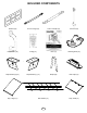
TOOLS REQUIRED DRILL 1/2” SOCKET & WRENCH HAMMER ADJUSTABLE WRENCH TAPE MEASURE SCREWDRIVER PHILLIPS BIT CARPENTER SQUARE SAFETY GLASSES 1/8” DRILL BIT INCLUDED HARDWARE 30mm Deck Screw (x82) 5/16” x 1-1/2” Lag Screw (x4) T-20 Bit (x1) 1-1/2” Deck Screw (x116) 1-1/4” Lag Screw (x44) 2-1/2” Deck Screw (x330) 2” Lag Screw (x42) #8 x 1/2” Pan Screw (x2) 3/4” Flat Head Screw (x40) 5/16” Loc Nut (x3) T-30 Bit (x1) #14 x 1” Truss Screw (x3) 5/16” Washer (x7) #12 x 3/4” Pan Screw (x22) 5
INCLUDED HARDWARE 1/4”-20 x 1-1/4” Hex Head Bolt (x8) 3/8’’ DRILL BIT 8mm Washer (x8) Weld-Nut (x8) 8mm Loc Washer (x8) 3/16” Tarp Washer (x22) INCLUDED COMPONENTS 4x4 Wrap Loc (x10) 4x4 Shelf Loc (x2) 6 2x4 Shelf Loc (x8)
INCLUDED COMPONENTS Window (x4) 23-1/4’’ Rungs (x3) Anchor It Strap (x4) Anchor It (x4) Play Handle (x2) ID Tag (x1) Plan (x1) Climbing Rock (x4) Step Bracket (R) (x1) Step Bracket (L) (x1) Staple (x6) Bolt Caps (x3) Tarp, Large (x1) Net Climber (x1) 7 Tarp, Small (x1)
(4) (7)[PF [PF4903] 4937]5/4’’ 5/4’’xx4’’ 6’’xx10-1/2’’ 47-1/2’’ (1) [PF(1)4942] 2’’ x 4’’5/8’’ x 17-1/2’’ [PF 4924] x 6’’ x 47-1/2’’ (2) 4’’ x 4’’ x 120’’ (8) [PF 4920] 5/8’’ x 6’’ x 40-1/2’’ (1) [PF 4922] 5/4’’ x 6’’ x 47’’ (1) [PF 4942] 2’’ x 4’’ x 17-1/2’’ [PF 4936] x 6’’ x 47’’ (2) [PF(1)4941] 2’’ x 4’’5/4’’ x 11’’ (5) [PF 5/8’’ x 6’’ x 36’’ (3) [PF 4935] 5/4’’ x 6’’ x 44’’ (5) [PF(1)4944] 2’’ x4919] 4’’5/8’’ x 47-1/2’’ [PF 4923] x x 47-1/2’’ LUMBER PURCHASED(2)SEPARATELY [PF 4941] 2’’ x 4’’ x6’’11’’
USE THE CORRECT FASTENER Use the guides below to help select the correct length, quantity & location of screws for the board installation. Avoid splitting your lumber by offsetting your screws at least 3/4” from edge. All hardware should be driven until flush with the surface or no deeper than 1/16”.
BRACKET INSTALLATION 4’’ x 4’’ Shelf-Loc bracket 1 2 3 CORRECT INCORRECT 2’’ x 4’’ Shelf-Loc bracket 1 2 3 CORRECT Bracket mounting NOTCH 1. Always use lag screws 2. Brackets interlock with each other. NEVER position them in a non-interlocking position. 3. Place lag screws in brackets only where instructed. Do NOT fill in every hole as this will lead to a hardware shortage.
STEP 1 4’’ x 4’’ x 120’’ 4’’ x 4’’ x 120’’ (2) 1-1/4” Lag Screws per bracket 59’’ 47’’ FRAME 1 1-1/4” Lag Screw (x8) 1. Attach brackets to posts as shown.
STEP 2 2’’ -1/ 47 FLUSH [PF ’ /2’ (3) 2-1/2’’ Screw Per Joint 5 4] 2 49 ’x /8’ x 6’’ -1 47 103-1/2’’ 4’’ x 4’’ x 120’’ 108’’ 49 ’’ x 5/4 -1 47 4’’ x 4’’ x 120’’ [PF ] 33 x 4’’ ’ /2’ Check to make sure structure is square FRAME 1 PRE-DRILL 2-1/2” Deck Screw (x12) 1. Assemble Frame 1 as shown. Note the bracket orientation.
STEP 3 (3) 1-1/4” Lag & (2) 2” Lag per 2x4 Shelf Loc bracket FLIP FRAME OVER FLUSH [PF ’’ ]2 44 49 ’’ x4 2’’ -1/ 7 x4 2’’ -1/ 47 FRAME 1 2” Lag Screw (x4) 1-1/4” Lag Screw (x6) 1. Attach support board to Frame 1 as shown.
STEP 4 Gap (2) 2” Lag Screws per bracket FLUSH 4’’ x 4’’ x 96’’ 4’’ x 4’’ x 96’’ (2) 1-1/4” Lag Screws per bracket 59’’ 1-1/4” Lag Screw (x4) FRAME 2 2” Lag Screw (x4) 1. Attach brackets to posts as shown.
STEP 5 CENTER HOLES CENTER HOLES 96’’ 21-7/8’’ 9-3/8’’ 12-1/2’’ 1. D rill (3) 3/8’’ holes in (1) 4’’ x 4’’ x 96’’ as shown. This will be used as the tower accessory arm.
STEP 6 T EN 1’’ TE NO x FLUSH 3] 91 4 [PF H ’’ ’’ x4 TIP: Flex bracket(s) to make installation of 4x4 easier 2’’ -1/ 7 x4 62-1/2’’ 4’’ x 4’’ x 96’’ (3) 2-1/2’’ Screw Per Joint ’’ 5/8 A PL 96 x 4’’ 4’’ x 4’’ x 96’’ 4’’ E OL M CE FLUSH [PF 2 49 ’’ x 1 9] 4’’ 2’’ -1/ 7 x4 (4) 2” Lag per 4x4 Shelf Loc bracket ’ /2’ -1 47 Check to make sure structure is square FRAME 2 2-1/2” Deck Screw (x12) PRE-DRILL 2” Lag Screw (x8) 1. Assemble Frame 2 as shown.
STEP 7 (3) 1-1/4” Lag & (2) 2” Lag per 2x4 Shelf Loc bracket FLIP FRAME OVER [PF 49 44 ]2 ’’ x FLUSH 4’’ x4 7-1 /2’ ’ FRAME 2 2” Lag Screw (x4) 1-1/4” Lag Screw (x6) 1. Attach support board to Frame 2 as shown.
STEP 8 FRAME 1 [PF 4913] 5/8’’ x 4’’ x 47-1/2’’ (3) 2-1/2’’ Screw FLUSH [PF 4913] 5/8’’ x 4’’ x 47-1/2’’ (3) 2-1/2’’ Screw (2) 2-1/2’’ Screw 62-1/2’’ [PF 1-3/4’’ [PF (2) 2-1/2’’ Screw 1-3/4’’ 49 28 ]1 ’’ x 4’’ x4 49 28 ]1 ’’ x 4’’ x4 5-3 /4’ ’ 5-3 /4’ ’ PRE-DRILL 2-1/2” Deck Screw (x10) 1. Attach support boards to Frame 1 as shown.
STEP 9 FRAME 2 (3) 2-1/2’’ Screw (3) 2-1/2’’ Screw (3) 2-1/2’’ Screw 6’’ /1 0-9 4 (3) 2-1/2’’ Screw FRAME 1 PRE-DRILL 2-1/2” Deck Screw (x12) 1. Attach Frame 1 to Frame 2 as shown.
STEP 10 (2) 2-1/2’’ Screw per joint ] 31 9 F4 ’’ 5/4 ’’ x4 2’’ -1/ 0 x4 [P ’ /2’ 1] 93 4 [PF ’’ x 5/4 4’’ x -1 40 (2) 2-1/2’’ Screw per joint PRE-DRILL 2-1/2” Deck Screw (x8) 1. Attach boards as shown.
STEP 11 x2 (2) 1-1/4” Lag Screws per bracket 47’’ 4’’ x 4’’ x96’’ 1-1/4” Lag Screw (x4) 1. Attach brackets to posts as shown.
STEP 12 47 -1/ [PF 49 23 2’’ ]5 /8’ ’x 6’’ x4 7-1 /2’ ’ FLUSH 4’’ x 4’’ x96’’ 4’’ x 4’’ x96’’ 78’’ [PF 49 29 ]1 (3) 2-1/2’’ Screw per joint ’’ x 4’’ x4 7-1 /2’ ’ FLUSH Check to make sure structure is square FRAME 3 PRE-DRILL 2-1/2” Deck Screw (x12) 1. Assemble Frame 3 as shown. Note the bracket orientation.
STEP 13 PRE-DRILL [PF 4917] 5/8’’ x 6’’ x 27’’ (3) 2-1/2’’ Screw (3) 1-1/4” Lag & (2) 2” Lag per 2x4 Shelf Loc bracket ALL BOARDS FLUSH WITH FACE OF POST [PF 4917] 5/8’’ x 6’’ x 27’’ (3) 2-1/2’’ Screw [PF 4943] 2’’ x 4’’ x 27’’ [PF 4943] 2’’ x 4’’ x 27’’ (3) 2-1/2’’ Screw [PF 4925] 1’’ x 4’’ x 25-1/4’’ [PF 4925] 1’’ x 4’’ x 25-1/4’’ (3) 2-1/2’’ Screw 2-1/2” Deck Screw (x12) 2” Lag Screw (x4) 1-1/4” Lag Screw (x6) 1. Attach support boards to Frame 3 as shown.
STEP 14 PRE-DRILL (3) 1-1/4” Lag & (2) 2” Lag per 2x4 Shelf Loc bracket (3) 2-1/2’’ Screw ’’ 27 (3) 2-1/2’’ Screw (2) 2-1/2’’ Screw (2) 2-1/2’’ Screw FRAME 3 2-1/2” Deck Screw (x10) 2” Lag Screw (x4) 1. Attach Frame 3 to Frame 1 as shown.
STEP 15 (2) [PF 4931] 5/4’’ x 4’’ x 40-1/2’’ (2) 2-1/2’’ Screw per joint (2) 2-1/2’’ Screw per joint PRE-DRILL 2-1/2” Deck Screw (x8) 1. Attach boards as shown.
STEP 16 (2) 2-1/2’’ Screw per joint (1) 2-1/2’’ Screw (2) [PF 4930] 5/4’’ x 4’’ x 40-1/4’’ [PF 4946] 1-1/2’’ x 1-5/8’’ x 27’’ Flush (2) 2-1/2’’ Screw per joint (2) 1-1/2’’ Screw per joint (1) 2-1/2’’ Screw (1) 2-1/2’’ Screw 1-1/2’’ 18’’ END VIEW (1) 2-1/2’’ Screw TOP VIEW 1-1/2” Deck Screw (x4) 2-1/2” Deck Screw (x10) 1. Attach boards as shown.
STEP 17 (4) 2-1/2’’ Screw per board (2) 1-1/2’’ Screw per board (1) [PF 4933] 5/4’’ x 4’’ x 47-1/2’’ (3) [PF 4937] 5/4’’ x 6’’ x 47-1/2’’ 1-1/2” Deck Screw (x8) 2-1/2” Deck Screw (x16) 1. Attach boards as shown.
STEP 18 [PF 4930] 5/4’’ x 4’’ x 40-1/4’’ (2) 2-1/2’’ Screw per joint [P F 49 44 ]2 ’’ x 4’’ x4 7- 1/2 ’’ [PF 4930] 5/4’’ x 4’’ x 40-1/4’’ (2) 2-1/2’’ Screw per joint (2) 2-1/2’’ Screw per joint (2) 2-1/2’’ Screw per joint 18’’ 2-1/2” Deck Screw (x16) TOP VIEW 1. Attach boards as shown.
STEP 19 [PF 4941] 2’’ x 4’’ x 11’’ Step Bracket (R) Step Bracket (L) 4-1/2’’ DETAIL OF STEP BRACKETS: (Left Bracket Shown) [PF 4941] 2’’ x 4’’ x 11’’ (3) 30 mm screws each bracket [PF 4942] 2’’ x 4’’ x 17-1/2’’ (3) 30 mm screws each bracket 30mm Deck Screw (x12) 1. Assemble Step as shown.
STEP 20 10’’ (2) 2-1/2’’ Screw per Joint (2) 2-1/2’’ Screw per Joint 2-1/2” Deck Screw (x8) UNDER DECK VIEW 1. Install step as shown.
STEP 21 3’’ [PF 49 13 ]5 /8’ ’x 4’’ x4 7-1 /2’ ’ (3) 2-1/2’’ Screw per Joint UNDER DECK VIEW PRE-DRILL 2-1/2” Deck Screw (x6) 1. Install Spacer Board as shown.
[PF 4937] 5/4’’ x 6’’ x 47-1/2’’ [PF 4937] 5/4’’ x 6’’ x 47-1/2’’ [PF 4935] 5/4’’ x 6’’ x 44’’ [PF 4935] 5/4’’ x 6’’ x 44’’ [PF 4935] 5/4’’ x 6’’ x 44’’ [PF 4937] 5/4’’ x 6’’ x 47-1/2’’ [PF 4937] 5/4’’ x 6’’ x 47-1/2’’ STEP 22 1/4’’ Gap Between All Deck Boards (6) 2-1/2’’ Screw per board TOP VIEW 2-1/2” Deck Screw (x42) 1. Install Deck Boards as shown.
OUTSIDE OF TOWER STEP 23 5/8’’ 5/8’’ [PF 4940] 1-1/2’’ x 1-5/8’’ x 35-1/2’’ 1-1/2’’ TOP VIEW BO T [PF TOM OF F 49 TO LUS 40] TO H DE P O CK F (4) 2-1/2’’ Screw per board 2-1/2” Deck Screw (x8) 1. Install Boards as shown.
OUTSIDE OF TOWER STEP 24 5/8’’ 5/8’’ 1-1/2’’ TOP VIEW [PF 4938] 1-1/2’’ x 1-5/8’’ x 10-1/4’’ 5/8’’ 14’’ (2) 2-1/2’’ Screw per board [PF 4938] 1-1/2’’ x 1-5/8’’ x 10-1/4’’ (2) 2-1/2’’ Screw per board [PF 4940] 1-1/2’’ x 1-5/8’’ x 35-1/2’’ (4) 2-1/2’’ Screw per board [PF 4940] 1-1/2’’ x 1-5/8’’ x 35-1/2’’ (4) 2-1/2’’ Screw per board FLUSH TO TOP OF DECK 2-1/2” Deck Screw (x12) 1. Install Boards as shown.
STEP 25 (5) [PF 4919] 5/8’’ x 6’’ x 36’’ 2-1/8’’ Gap Between Barrier Boards (2) 2-1/2’’ Screw per board (2) 30mm Screw per board FLUSH 30mm Deck Screw (x10) 2-1/2” Deck Screw (x10) 1. Install Boards as shown.
STEP 26 (2) 1-1/2’’ Screw per joint PRE-DRILL [PF 4920] 5/8’’ x 6’’ x 40-1/2’’ [PF 4914] 5/8’’ x 6’’ x 12-7/8’’ [PF 4914] 5/8’’ x 6’’ x 12-7/8’’ 1/8’’ GAP [PF 4907] 5/8’’ x 4’’ x 12-7/8’’ [PF 4914] 5/8’’ x 6’’ x 12-7/8’’ [PF 4914] 5/8’’ x 6’’ x 12-7/8’’ 1/8’’ GAP [PF 4920] 5/8’’ x 6’’ x 40-1/2’’ [PF 4920] 5/8’’ x 6’’ x 40-1/2’’ [PF 4920] 5/8’’ x 6’’ x 40-1/2’’ SIDE VIEW 1-1/2” Deck Screw (x28) 1. Install Boards as shown.
STEP 27 PRE-DRILL (2) 1-1/2’’ Screw per joint [PF 4920] 5/8’’ x 6’’ x 40-1/2’’ [PF 4914] 5/8’’ x 6’’ x 12-7/8’’ [PF 4914] 5/8’’ x 6’’ x 12-7/8’’ 1/8’’ GAP [PF 4907] 5/8’’ x 4’’ x 12-7/8’’ [PF 4914] 5/8’’ x 6’’ x 12-7/8’’ [PF 4914] 5/8’’ x 6’’ x 12-7/8’’ [PF 4920] 5/8’’ x 6’’ x 40-1/2’’ [PF 4920] 5/8’’ x 6’’ x 40-1/2’’ [PF 4920] 5/8’’ x 6’’ x 40-1/2’’ SIDE VIEW 1-1/2” Deck Screw (x28) 1. Install Boards as shown.
STEP 28 (2) Window Frames (16) 3/4’’ Flat Head Screws (2) Window Frames (16) 3/4’’ Flat Head Screws 3/4” Flat Head Screw (x32) 1. Attach window frame as shown.
STEP 29 [PF 4904] 5/8’’ x 3’’ x 14-3/4’’ (4) 3/4’’ Flat Head Screws Per Board SECURE BOARD THROUGH WINDOW FRAMES [PF 4904] 5/8’’ x 3’’ x 14-3/4’’ 3/4” Flat Head Screw (x8) 1. Attach Boards as shown.
STEP 30 (2) [PF 4905] 5/8’’ x 4’’ x 10-1/2’’ (3) 2-1/2’’ Screws Per Board FLUSH (2) 1-1/2’’ Screws Pre-Drill PRE-DRILL (2) [PF 4918] 5/8’’ x 6’’ x 30’’ (2) 30mm Screws Per Joint FLUSH 30mm Deck Screw (x8) 1-1/2” Deck Screw (x2) 2-1/2” Deck Screw (x6) 1. Attach Boards as shown. Note: If a slide was not purchased, please see barrier assembly on page 55.
STEP 31 (2) [PF 4906] 5/8’’ x 4’’ x 12-3/8’’ (3) 2-1/2’’ Screws Per Board FLUSH (2) 1-1/2’’ Screws Pre-Drill PRE-DRILL (2) [PF 4911] 5/8’’ x 4’’ x 42’’ (2) 30mm Screws Per Joint (2) [PF 4921] 5/8’’ x 6’’ x 42’’ (2) 30mm Screws Per Joint FLUSH 30mm Deck Screw (x16) 1-1/2” Deck Screw (x2) 1. Attach Boards as shown.
STEP 32 8-3/4’’ [PF 4939] 1-1/2’’ x 1-5/8’’ x 30’’ (4) 1-1/2’’ Screws (2) [PF 4940] 1-1/2’’ x 1-5/8’’ x 35-1/2’’ (4) 1-1/2’’ Screws Per Board Secure boards in place by mounting from inside tower. FLUSH 1-1/2’’ 1-5/8’’ END VIEW [PF 4912] 5/8’’ x 4’’ x 43-1/4’’ (2) 1-1/2’’ Screws Per Joint PRE-DRILL 3/4’’ FROM TOP OF POST 1-1/2” Deck Screw (x16) 1. Attach Boards as shown.
STEP 33 [PF 4915] 5/8’’ x 6’’ x 17-7/8’’ (2) 1-1/2’’ Screws [PF 4910] 5/8’’ x 4’’ x 4-1/4’’ (2) 1-1/2’’ Screws [PF 4910] 5/8’’ x 4’’ x 4-1/4’’ (2) 1-1/2’’ Screws [PF 4909] 5/8’’ x 6’’ x 17-7/8’’ (2) 1-1/2’’ Screws 12-5/8’’ PRE-DRILL [PF 4926] 1’’ x 4’’ x 31-1/2’’ [PF 4926] 1’’ x 4’’ x 31-1/2’’ (6) 1-1/2’’ Screws (6) 1-1/2’’ Screws FLUSH ON BOTTOM EDGE [PF 4939] 1-1/2’’ x 1-5/8’’ x 30’’ [PF 4939] 1-1/2’’ x 1-5/8’’ x 30’’ [PF 4927] 1’’ x 4’’ x 31-1/2’’ [PF 4927] 1’’ x 4’’ x 31-1/2’’ 17’’ 17’’ 1-
STEP 34 PRE-DRILL (2) 2-1/2’’ Screws (4) 30mm Screws Per Side 1-1/4’’ (2) 2-1/2’’ Screws [PF 4933] 5/4’’ x 4’’ x 47-1/2’’ (2) 2-1/2’’ Screws Per Joint 30mm Deck Screw (x8) 2-1/2” Deck Screw (x12) 1. Attach Boards as shown.
STEP 35 (2) 30mm Screws (3) 2-1/2’’ Screws Per Joint (2) 30mm Screws [PF 4932] 1’’ x 4’’ x 42-7/8’’ FLUSH (3) 2-1/2’’ Screws Per Joint (2) 2-1/2’’ Screws FLUSH [PF 4932] 1’’ x 4’’ x 42-7/8’’ [PF 4933] 5/4’’ x 4’’ x 47-1/2’’ (2) 2-1/2’’ Screws PRE-DRILL 30mm Deck Screw (x4) 2-1/2” Deck Screw (x16) 1. Attach Boards as shown.
STEP 36 Tarp, Large #12 x 3/4” Pan Screw #12 x 3/4” Pan Screw 3/16” Tarp Washer 3/16” Washer Tarp, Small 3/16” Tarp Washer #12 x 3/4” Pan Screw #12 x 3/4” Pan Screw (x22) 1. Attach Tarps as shown.
STEP 37 CURVED SIDE UNDER DECK FLAT SIDE OUTWARD 11-1/8’’ 11-1/8’’ 10-3/8’’ (3) 23-1/4’’ Rungs (2) 2’’ Lag Screws Per Rung SIDE VIEW 1-3/8’’ (2) [PF 4908] 5/8’’ x 4’’ x 27’’ (3) 2-1/2’’ Screws Per Joint UNDER DECK VIEW 2” Lag Screw (x6) PRE-DRILL 1. Attach Ladder Rungs and spacer Boards as shown.
STEP 38 19-1/2’’ FLUSH (2) PF 4944 2’’x4’’x47-1/2’’ ROCK WALL (8) PF 4916 5/8’’x6’’x20’’ ROCK WALL 3-1/2’’ Gap Bottom CENTER BOARDS (2) 2-1/2’’ Screws Per Joint (2) 2-1/2’’ Screws Per Joint (2) Weld Nuts x4 Underdeck View (2) 1-1/4’’ Hex Head Bolts PRE-DRILL (1) Climbing Rock (2) 8mm Loc-Washer Per Rock (2) 8mm Flat Washer Per Rock 2-1/2” Deck Screw (x36) 1. Assemble Rock Wall as shown. Center 5/8’’ boards evenly on 2’’ x 4’’ supports. 2.
STEP 39 1-1/2’’ 3’’ (2) PF 4903 5/4’’x4’’x10-1/2’’ (2) 1-1/2’’ Screws Per Joint PF 4922 5/8’’x6’’x47’’ 3-1/2’’ PICNIC TABLE 2-5/8’’ MAX PICNIC BENCH 1-1/2’’ PRE-DRILL 3-1/2’’ TOP VIEW (2) PF 4903 5/4’’x4’’x10-1/2’’ (2) 1-1/2’’ Screws Per Joint PF 4936 5/4’’x6’’x47’’ 3’’ 16’’ FLUSH (3) 2-1/2’’ Screws Per Joint PICNIC BENCH 1-1/2” Deck Screw (x8) 2-1/2” Deck Screw (x12) 1. Assemble Picnic Table and Bench as shown. Attach Picnic Bench as shown.
STEP 40 PICNIC TABLE FLUSH (3) 2-1/2’’ Screws Per Joint 28-1/2’’ PRE-DRILL FLUSH WITH FACE OF UPRIGHT (4) 2’’ Lag Screws 4’’ x 4’’ x 96’’ 2” Lag Screw (x4) 2-1/2” Deck Screw (x6) 1. Attach Picnic Table and Climber Support Board as shown.
STEP 41 (3) 5/16’’ Flat Washer (3) 5/16’’ Loc-Nut (1) Net Climber (2) 30mm screw Per Cap 4’’ x 4’’ x 96 ’’ (2) Staples 1’’ 1’’ 30mm Deck Screw (x6) 1. Attach Net Climber as shown. 2. Attach bolt covers over loc nuts at all three locations as shown. 3. Use two rope staples to secure the bottom of each Pirate’s Ladder rope. Tap two staples in place approximately 1’’ apart. Wrap the rope under the 4’’ x 4’’. Then thread the rope through both staples.
STEP 42 #14 x 1” Truss Screws With hammer pound stake into ground as shown. Grade 2” (2) 30mm Deck Screws PF 4338 2’’x2’’x17’’ Slide Stake 30mm Deck Screw (x2) #14 x 1 ‘‘ Truss Screw (x3) 1. Attach slide as shown.
STEP 43 (1) Play Handle (1) Play Handle (2) 1-1/4’’ Lag Screw (2) 1-1/4’’ Lag Screw 11” 11” (1) ID TAG (2) 1/2’’ Pan Screw 1-1/4” Lag Screw (x4) 1/2” Pan Screw (x2) 1. Attach Play Handle as shown centered on upright. 2. Attach ID Tag as shown.
STEP 44 x4 5/16” Washer Fold up Anchor-It Strap x4 1-1/2” Lag Screw Anchor-It 5/16 x 1-1/2” Lag Screw (x4) 1. Place swing set in final location and mount Anchor-It(s) at locations circled above. 2. Twist the Anchor-It into the ground until only the loop is exposed. 3. Place Anchor-It Strap thru loop, fold the ends together and attach to the unit as shown. Note: Keep as little play as possible using any of the holes in the strap that work best.
NO SLIDE 1-1/2’’ Gap Between Barrier Boards FLUSH FLUSH (4) 30mm Screws Per Board (4) 5/4’’ x 6’’ x 30’’ (1) 1’’ x 4’’ x 47-1/2’’ (4) 30mm wood screws per board (3) 2-1/2’’ wood screws APPLY HARDWARE FROM OUTSIDE OF UNIT. 30mm Deck Screw (x16) 2-1/2” Deck Screw (x6) 47-1/2'' (1) 1'' x 4'' x 96'' 30'' 30'' 30'' (1) 5/4'' x 6'' x 120'' If no slide is purchased, additional lumber will be needed to complete the assembly.
800•888•1232 Got Questions? We’ve got answers! Call our Customer Support Representatives Available Monday - Friday, 7am - 5pm (CST) Weekend support available April through Labor Day Also available on Memorial Day, Fourth of July & Labor Day Technical Support from experienced Swing-N-Slide Customer Service Representatives who have actually built a swing set themselves.