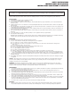
NOTE: THIS PAGE REPLACES PAGE 15 IN YOUR PLAN 2'' x 4'' x 26'' FLUSH 2'' x 4'' x 78'' 21 '' (2) 16D galvanized nails per joint (2) 16D galvanized nails per joint Fig. 8 B. Ladder Assembly Fig. 8a Fig. 9 1. Install 2'' x 4'' x 78'' Ladder Support Board as shown in (Fig. 8). 2. Install 2'' x 4'' x 26'' Ladder Spacer Board as shown in (Fig. 8a). 3. Attach Metal Ladder Rungs as shown in (Fig. 9).
R Wrangler See back page for Lumber RequiredBill of Materials Ver al dorso para determinar la madera necesaria Cuenta de materiales Voir au verso pour les pièces de bois requises Liste des matériaux ASSEMBLY INSTRUCTIONS INSTRUCCIONES PARA ARMAR DIRECTIVES D’ASSEMBLAGE Swing•N•Slide • 1212 Barberry Drive • Janesville, Wisconsin 53545 www.swing-n-slide.
SAFETY INSTRUCTIONS INSTRUCCIONES DE SEGURIDAD INSTRUCTIONS CONCERNANT LA SÉCURITÉ IMPORTANT!This product is intended for single family residential use only and not intended for use in any publi setting. Placement in any public setting constitutes a misuse of this product. REQUIRED SAFETY INSTALLATION INSTRUCTIONS • Once the unit is completely assembled and before children are allowed to play on it, proper shock-absorbing surfacing material must be installed.
SAFETY INSTRUCTIONS INSTRUCCIONES DE SEGURIDAD INSTRUCTIONS CONCERNANT LA SÉCURITÉ PARENTS: Before building a backyard play area please take the time to read all instructions completely and caution your children accordingly. Observing the following statements and warnings reduces the likelihood of serious injury. When building this kit, at least two people are required for lifting and holding beams, frames or other heavy assemblies in position before bolting or nailing.
SAFETY INSTRUCTIONS INSTRUCCIONES DE SEGURIDAD INSTRUCTIONS CONCERNANT LA SÉCURITÉ PADRES: Antes de hacer un lugar para recreo en su traspatio por favor tome el tiempo necesario para leer todas las instrucciones completamente y así advertir a sus hijos. Observando los siguientes párrafos de advertencias reduce la posibilidad de que hayan lesiones graves.
SAFETY INSTRUCTIONS INSTRUCCIONES DE SEGURIDAD INSTRUCTIONS CONCERNANT LA SÉCURITÉ AVIS AUX PARENTS : Avant d’installer un équipement de jeu dans la cour, bien lire toutes les instructions au complet et transmettre aux enfants les mises en garde qui s’imposent. L’observation des mesures de sécurité et des mises en garde qui suivent permet de réduire les risques de blessures graves.
TOOLS REQUIRED HERRAMIENTAS REQUERIDAS OUTILS REQUIS CIRCULAR SAW SIERRA CIRCULAR SCIE CIRCULAIRE ELECTRIC DRILL TALADRO ELÉCTRICO PERCEUSE ÉLECTRIQUE 1/2" SOCKET & WRENCH CUBO DE 1/2" DE LLAVE DE TRINQUETE DOUILLE ET CLÉ DE 1/2 po HAMMER MARTILLO MARTEAU TAPE MEASURE CINTA MÉTRICA RUBAN À MESURER SAFETY GLASSES & DUST MASK ANTEOJOS DE SEGURIDAD Y MÁSCARA DE POLVO LUNETTE DE PROTECTION ET MASQUE À POUSSIÈRE 5/16" DRILL BIT (LONG) PUNTA DE TALADRO DE 5/16" (LARGA) FORET DE 5/16 po (LONG) PHILLIPS BIT
Minimum Use Zone • Zona mínima de uso • Zone d'utilisation minimum Minimum Use Zone - Wrangler Zona mínima de uso - Wrangler Zone d'utilisation minimum – « Wrangler » No. of Children: Up to 5 Min. Use Zone: 29' x 30' Set Dim. 14'W x 17'L x 11'H Est. Building Time: 4-6 hr. No. de niños: Hasta 5 Zona de uso mínimo: 29' x 30' Dim. del conjunto: 14' An x 17' L x 11' Al Tiempo Est. de construcción: 4-6 horas 30' Nb d’enfants : Jusqu’à 5 Zone min. d’util. : 29 pi x 30 pi Dim.
CUTTING GUIDE GUÍA DE CORTAR GUIDE DE COUPE 26" 18" 18" (1) 2" x 4" x 8' • 2" x 4" x 8' • 2 po x 4 po 8 pi 60" 58-1/2" (1) 2" x 4" x 10' • 2" x 4" x 10' • 2 po x 4 po 10 pi 57" 57" 5-1/2" (2) 2" x 4" x 10' • 2" x 4" x 10' • 2 po x 4 po 10 pi 60" 60" 18" 5-1/2" (1) 2" x 4" x 12' • 2" x 4" x 12' • 2 po x 4 po 12 pi 32" 34" 37" 18" 18" (1) 2" x 4" x 12' • 2" x 4" x 12' • 2 po x 4 po 12 pi 30-1/4" 30-1/4" 27-1/2" 50" (1) 2" x 4" x 12' • 2" x 4" x 12' • 2 po x 4 po 12 pi 78" 32-1/2" 32-1/
ASSEMBLY INSTRUCTIONS INSTRUCCIONES PARA ARMAR DIRECTIVES D’ASSEMBLAGE o o o o o o 2" x 6" x 96" o o 4" 1. Examine the assembly instructions carefully and familiarize yourself with the illustrations. Flip the frame to attach the 2” x 6” x 57” deck support Voltear la estructura para unir el soporte de plataforma de 2" x 6" x 57" Retourner le cadre pour installer le 2 po x 6 po x 57 po thex frame to dans le (50 mm xFlip 150 mm 1,448 mm) centre telthe qu'illustré à lax(fig. attach 2" x 6" 57" 2.
ASSEMBLY INSTRUCTIONS INSTRUCCIONES PARA ARMAR DIRECTIVES D’ASSEMBLAGE Fig. 2 2 Frame 2 Fig. o o o o 2" x 4" x 60" o o o o o o o o 1-1/2" overlap 1-1/2" de traslapo Chevauchement de 1 1/2 po (38 mm) 3. On a flat work surface, lay out three 4" x 4" x 8' legs, 2" x 4" x 60" top support and 2" x 6" x 60" bottom support as indicated in Fig. 2. Follow dimensions in Fig. 2 for proper lumber placement. Make sure frame assembly is 90° square then nail lumber together using four 16D galvanized nails per joint.
ASSEMBLY INSTRUCTIONS INSTRUCCIONES PARA ARMAR DIRECTIVES D’ASSEMBLAGE A. Frame Assembly (cont.) 4. Lay Frame 2 on a level surface as shown in Fig. 3. Attach the bottom two 2" x 6" x 57" ground supports using four 16D galvanized nails per joint. NOTE: The edges of the 2" x 6" x 57" should be flush with the outside edge of the corresponding 2" x 6" boards of Frame 2 (see Fig. 3).
ASSEMBLY INSTRUCTIONS INSTRUCCIONES PARA ARMAR DIRECTIVES D’ASSEMBLAGE Fig. 4 Fig. 2" x 4" x 57" 2" x 4" x 58-1/2" FRAME 1 A. Assemblage des cadres (suite) 4. Déposer le cadre 2 sur une surface à niveau tel qu'illustré à la fig. 3. Fixer les deux supports inférieurs de 2 po x 6 po x 57 po (50 mm x 150 mm x 1,45 m) à l'aide de quatre clous galvanisés 16D par joint.
ASSEMBLY INSTRUCTIONS INSTRUCCIONES PARA ARMAR DIRECTIVES D’ASSEMBLAGE Fig. 5 22-1/2" 2" x 6" x 57" Offset counter-bored holes 1/2'' Desfasar los agujeros de contra aberturas en 1/2" Offsetles counter-bored Décaler trous chambrés de 1/2 po (12 mm) Fig.6 6 Fig.
ASSEMBLY INSTRUCTIONS INSTRUCCIONES PARA ARMAR DIRECTIVES D’ASSEMBLAGE A. Frame Assembly 10. Position the 2" x 6" x 57" deck support between the frames as indicated in Fig 5, approximately 22-1/2" from the outside deck support. The top of the deck support should be flush with the corresponding boards it will be attached to. 11. Attach the deck support to the frame assembly using three 16D galvanized nails per joint. NOTE: Center nails on the joint to assure the nails do not split the wood. 12.
ASSEMBLY INSTRUCTIONS INSTRUCCIONES PARA ARMAR DIRECTIVES D’ASSEMBLAGE B. Ladder Assembly 1. See Figs. 8 & 9 for ladder locations. On a 2" x 4" x 78" board, mark rung holes as dimensioned in Fig. 7. Drill holes through the 2" x 4" using a 1-1/8" spade bit. 2. Place the 2" x 4" x 78" board against the 4" x 4" leg of the frame as shown in Fig. 8. Using the 2" x 4" as a template, mark hole locations on the 4" x 4" leg.
ASSEMBLY INSTRUCTIONS INSTRUCCIONES PARA ARMAR DIRECTIVES D’ASSEMBLAGE Fig.Fig. 7 7 78" 14-1/2" 11" 11" top B. Montaje de la escalera 1. Ver la Fig. 8 y la 9 para las ubicaciones de las escaleras. Sobre un plano de 2" x 4" x 78", marcar los agujeros de los peldaños según las dimensiones de la Fig. 7. Taladrar agujeros a través del 2" x 4" usando una broca con punta de lanza de 1-1/8". 2. Colocar el plano de 2" x 4" x 78" contra la pata de 4" x 4" de la estructura como se muestra en la Fig. 8.
ASSEMBLY INSTRUCTIONS INSTRUCCIONES PARA ARMAR DIRECTIVES D’ASSEMBLAGE C. Deck Assembly 1. Position two 2" x 4" x 5-1/2" blocks against the side of the 2" x 4" x 78" ladder support and the 4' x 4" frame post as indicated in Fig. 10. Attach the 2" x 4" x 5-1/2" block to the support and post using four 10D galvanized nails. NOTE: The top s of the 2" x 4" x 51/2" boards should be flush with the top of the corresponding 2" x 6" x 57" deck support. 2" x 4" x 37" 2.
ASSEMBLY INSTRUCTIONS INSTRUCCIONES PARA ARMAR DIRECTIVES D’ASSEMBLAGE C. Montaje de la plataforma C. Assemblage de la plate-forme 1. Posicionar dos bloques de 2" x 4" x 5-1/2" contra el lado del soporte de la escalera de 2" x 4" x 78" y el poste de la estructura de 4' x 4" como se indica en la Fig. 10. Unir el bloque de 2" x 4" x 5-1/2" al soporte y al poste utilizando cuatro clavos 10D galvanizados.
ASSEMBLY INSTRUCTIONS INSTRUCCIONES PARA ARMAR DIRECTIVES D’ASSEMBLAGE Assembly Instructions 1. Position two 2" x 4" x 32-1/2" railing supports on the unit as indicated in Fig. 13. Boards should be flush with the edges of the 4" x 4" post and ladder upright and the bottom 2" x 4" x 32-1/2" should be even with the deck board. NOTE: The top of the upper rail should be approximately 30" from the bottom of the lower rail.
ASSEMBLY INSTRUCTIONS INSTRUCCIONES PARA ARMAR DIRECTIVES D’ASSEMBLAGE D. Montaje del riel D. Assemblage de la rampe 1. Poner dos soportes de pasamanos de 2" x 4" x 32-1/2" en la unidad como se indica en la Fig. 13. Los planos deben estar al ras con los bordes del poste de 4" x 4" y la escalera erguida y la parte inferior de 2" x 4" x 32-1/2" deben estar nivelados con el plano de la plataforma.
ASSEMBLY INSTRUCTIONS INSTRUCCIONES PARA ARMAR DIRECTIVES D’ASSEMBLAGE Assembly Instructions D. Railing Assembly (cont.) 5. Evenly space six 5/4" x 6" x 30" rails between the posts of the unit as indicated in Fig. 14. Attach the rails to the support using two 8D galvanized nails per joint. Fig.14 14 Fig. 5/4" x 6" x 30" 5/4" x 6" x 30" 6. Place five 5/4" x 6" x 30" rails on the side of the kit with the center post. As indicated in Fig.
ASSEMBLY INSTRUCTIONS INSTRUCCIONES PARA ARMAR DIRECTIVES D’ASSEMBLAGE D. Montaje de riel (cont.) D. Assemblage de la rampe (suite) 5. Distribuir uniformemente seis rieles de 5/4" x 6" x 30" entre los postes de la unidad como se indica en la Fig. 14. Unir los rieles al soporte utilizando dos clavos 8D galvanizados por junta. 5. Espacer uniformément six rampes de 5/4 po x 6 po x 30 po (32 mm x 150 mm x 762 mm) entre les poteaux de l'unité tel qu'indiqué à la fig. 14.
ASSEMBLY INSTRUCTIONS INSTRUCCIONES PARA ARMAR DIRECTIVES D’ASSEMBLAGE Fig. 19 EZ Frame Bracket Fig.Fig. 1819 4" x 4" x 8' 4" x 4" x 8' Align the edges of the 4" x 4" legs with the edges of EZ Frame Bracket 24-1/2" Alinee las patas del 4" x 4" con los filos del sostén de armazón EZ 2" x 6" x 72" Aligner le bord des montants de 4 x 4 po avec les bords du support EZ Frame 94-1/2" F. A-Frame Assembly 1. Measure the 4" x 4" x 8' legs to insure they are the same length. Adjust if necessary.
ASSEMBLY INSTRUCTIONS INSTRUCCIONES PARA ARMAR DIRECTIVES D’ASSEMBLAGE 2" 142" 5-1/2" 136-1/2" 12-1/2" l Indicates placement of a beam cover only placement of a beam l IndicaIndicates solamente la ubicación decover unaonly cubierta de viga l Indique la pose d'une enveloppe de poutre seulement Indicates placement of beam cover and bottom beam clamp n Indicates placement of beam cover and bottom beam clamp Note: leftcubierta side of the n Indica la Dimensions ubicación on dethe una debeam vigaindicate y u
ASSEMBLY INSTRUCTIONS INSTRUCCIONES PARA ARMAR DIRECTIVES D’ASSEMBLAGE G. Beam Assembly 1. If you are using a 2" x 6" laminated beam refer to page 27. 2. Measure and mark all holes on the center of the 4" x 6" x 12' beam as dimensioned in Fig. 24. 3. Using a 5/16" drill bit, drill holes through the beam at a 90° angle to the lumber. NOTE: If drill bit is not long enough, measure and mark the top of the beam and drill from both sides. 4.
ASSEMBLY INSTRUCTIONS INSTRUCCIONES PARA ARMAR DIRECTIVES D’ASSEMBLAGE Fig. 22 Fig. 23 10D galv. nails beam cover loc nut washer NOTE: You will need the assistance of at least one other individual to correctly attach the beam to the A-Frame assembly. NOTA: usted va a requerir ayuda de por lo menos una persona más para unir correctamente la viga al montaje de la estructura en A. REMARQUE : il faudra l'aide d'au moins une autre personne pour installer correctement la poutre au cadre en A. H.
ASSEMBLY INSTRUCTIONS INSTRUCCIONES PARA ARMAR DIRECTIVES D’ASSEMBLAGE NOTE: Lay the lumber on a flat surface before beginning laminated beam assembly. NOTA: disponer las maderas sobre una superficie plana antes de comenzar el montaje de la viga laminada. REMARQUE : déposer les pièces de bois sur une surface a plat avant de commencer l'assemblage d'une poutre laminée. Fig. 24 24" NOTE: Nail one end of the beam with one nail, realign boards and nail the other end.
ASSEMBLY INSTRUCTIONS INSTRUCCIONES PARA ARMAR DIRECTIVES D’ASSEMBLAGE Assembly Fig. 26 92" J. Attaching Beam 1. Position the beam brace on the 4" x 4" x 96" center post and 4" x 6" beam and mark the position of the holes on each (Fig. 26). NOTE: The top of the beam should be 92" from the bottom of the climbing unit (Fig. 26). 2. Drill a 1-1/8" counterbore, 1" deep, at each hole location as indicated in Fig. 27. 3.
ASSEMBLY INSTRUCTIONS INSTRUCCIONES PARA ARMAR DIRECTIVES D’ASSEMBLAGE Fig. 28 Fig. 29 REMOVE QUITE À ENLEVER REMOVE QUITE À ENLEVER NEVER hang a swing seat by a partial link of chain! Remove and discard partial links. ¡NUNCA cuelgue un asiento de columpio en un eslabón parcial de la cadena! Quite y deseche eslabones parciales. Ne JAMAIS suspendre une balançoire par un maillon incomplet! Enlever et jeter les maillons incomplets. Fig. 30 K. Final Assembly 1.
ASSEMBLY INSTRUCTIONS INSTRUCCIONES PARA ARMAR DIRECTIVES D’ASSEMBLAGE Fig. 32 Fig. 32 Stake Here Colocar las estacas aquí Piquet ici Stake Here Stake Here Stake Here Colocar las estacas aquí Piquet ici StakeHere Here Stake Colocar las estacas aquí Piquet ici L. Staking 1. Position three 18" stakes as indicated in Fig. 32. NOTE: Place the stakes next to the outside of the A-frame legs and the backside of the ladder corner post of the Wrangler.
ASSEMBLY INSTRUCTIONS INSTRUCCIONES PARA ARMAR DIRECTIVES D’ASSEMBLAGE M. Safety Handles Fig. 33 1. Position Safety Handles in the ladder opening. The bottom hole of the safety handle should be 8" from the top of the deck. Mark the hole locations and drill a pilot hole at each location using a 1/8" drill bit. Attach safety handles to the unit using two 1-3/4" screws and 1/4" washers per handle (see Fig. 33). 2. Position Name Plate in a prominent location and attach using two 1/2" panhead screws. M.
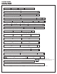
Madera requerida Cuenta de materiales Lumber Required Bill of Materials Qty.