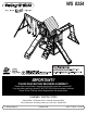
WS 8354 IMPORTANT!! PLEASE READ BEFORE BEGINNING ASSEMBLY!! Please make sure all lumber, hardware and accessory parts are accounted for. If you are missing anything, please DO NOT RETURN to the store where purchased. Please call our Customer Service Department at the number below. ASSEMBLY INSTRUCTIONS Swing•N•Slide • 1212 Barberry Drive • Janesville, Wisconsin 53545 Visit our web site at: www.swing-n-slide.com or call us at 1-800-888-1232 © Swing-N-Slide Inc.
Safety Checklist for Swing-N-Slide Play Sets and Accessories Observing the following statesments and warnings reduces the likelihood of serious or fatal injury This playset has been designed for use by a maximum of fifteen (15) occupants at one time having a combined weight of 1,575 pounds. This playset is intended for use by children from (2) to (10) years of age. On-site adult supervision for children of all ages is recommended.
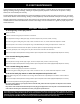
PLAYSET MAINTENANCE Cosmetic defects that do not affect the structural integrity of the product, or natural defects of wood such as warping, splitting, checking, twisting, shrinkage, swelling or any other physical properties of wood that do not present a safety hazard, are not covered by our warranty. To help minimize these natural defects we recommend applying a sealer or stain every two or three years, or more often as the climate dictates.
PLAYGROUND SURFACING MATERIALS SECTION 4 OF THE CONSUMER PRODUCT SAFETY COMMISSION'S OUTDOOR HOME PLAYGROUND SAFETY HANDBOOK9 Select Protective Surfacing One of the most important things you can do to reduce the likelihood of serious head injuries is to install shock-absorbing protective surfacing under and around your play equipment. The protective surfacing should be applied to a depth that is suitable for the equipment height in accordance with ASTM Specification F 1292.
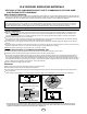
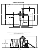
PLAYEST SAFETY ZONE 6'-0" 14'-0" 28'-0" 6'-0" 16'-4 3/4" 28'-6 1/16" 6'-0" 14'-0" 6'-0" 6'-0" 20'-10" 32'-10" MINIMUM USE ZONE FOR PLAY EQUIPMENT SHALL EXTEND NO LESS THAN 72” FROM ALL SIDES OF THE PLAY STRUCTURE. SWING USE ZONE EXTENDS NO LESS THAN 168”. SWINGS MUST HAVE A MINIMUM CLEARANCE OF 8” ABOVE THE PROTECTIVE SURFACING.
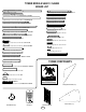
TOOLS REQUIRED DRILL 1/2” & 7/16’’ SOCKETS & WRENCH HAMMER ADJUSTABLE WRENCH TAPE MEASURE SCREWDRIVER PHILLIPS BIT CARPENTER SQUARE SAFETY GLASSES 1/8” DRILL BIT HELPFUL ASSEMBLY INFORMATION Your playset consists of several boxes or modules. It is important to ensure all lumber, accessories and hardware is accounted for. The following pages list the contents of each box. Use these pages to take an inventory of all parts.
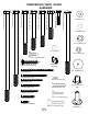
(2) [PF 6010] 1’’ x 3-3/8’’ x 47-1/2’’ TOWER MODULE: SA6000 / SA6022 TOWER MODULE SA6051 / SA6022 (1) [PF 6011] 1’’ x 3-3/8’’ x 47-1/2’’ BOARD LIST (4) [PF 6062] 1’’ x 3-3/8’’ x 42-1/2’’ ROOF A-FRAME (4) [PF 6164] 3’’ x 3’’ x 94’’ (7) [PF 6008] 3/4’’3/4’’ x 5-3/8’’ x 42’’ (2) [PF 6063] x 3-3/8’’ x 59-5/8’’ A-FRAME BASE (1) [PF 6020] 3’’ x 3’’ x 47-1/2’’ SWING BEAM SUPPORT (3) [PF 6006] x 3-3/8’’ x 44-1/2’’ (2) [PF 6013] 5/8’’3/4’’ x 5-3/8’’ x 22-3/4’’ ROCKWALL BOARD (1) [PF 6019] 2-11/16’’ x 5-3/8’’
TOWER MODULE SA6051 / SA6022 COMPONENTS CONT.
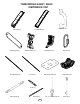
7’’ 6’’ 4’’ 3 1/2’’ 3 1/4’’ 2 1/2’’ TOWER MODULE SA6051 / SA6022 HARDWARE 5/16”-18 x 6” Carriage Bolt (x3) 1/4”-20 x 1-1/4” Hex Bolt (x12) 5/16”-18 x 2-1/2” Hex Bolt (x2) 5/16”-18 x 3-1/4” Hex Bolt (x2) 5/16”-18 x 3-1/2” Hex Bolt (x4) 5/16”-18 x 4” Hex Bolt (x5) 5/16”-18 x 7” Hex Bolt (x1) 5/16”-18 x 8-1/2” Hex Bolt (x1) 1/4’’ Washer (x16) 5/16” Washer (x24) 5/16’’ Loc Washer (x12) 5/16” Loc Nut (x9) 1/4’’ Loc Washer (x12) #12 x 3/4” Truss Screw (x14) FS2831 FS2831 FS2831 FS2831 3FS2831 3
/16’’ x 3’’ x 62’’ A-FRAME SUPPORT (2) [PF 6060] 5/8’’ x 5-3/8’’ x 13’’ SUN ’’ x 3-3/8’’ x 83’’ A-FRAME LEGS ’’ x 3-3/8’’ x 60’’ ROCKWALL SUPPORT 8’’ x 3-3/8’’ x 58’’ A-FRAME SUPPORT TERRACE MODULE SA6001 (4) [PF 6001] 5/8’’ x 5-3/8’’ x 9-1/4’’ BOARD LIST TERRACE MODULE: SA6001 (1) [PF 6061] 1-1/2’’ x 1-1/2’’ x 40’’ (2) [PF 6028] 1-3/8’’ x 3’’ x 79’’ 8’’ x 3-3/8’’ x 43-1/2’’ 8’’ x 3-3/8’’ x 17-1/4’’ SLIDE STAKE 8’’ x 3-3/8’’ x 15-1/2’’ DECK SUPPORT (2) [PF 6026] 1’’ x 3-3/8’’ x 42’’ (3) [PF 6005] 3/
(5) [PF 6005] 3/4’’ x 3-3/8’’ x 42’’ (1) [PF 6034] 1-3/8’’ x 3-3/8’’ x 66-1/4’’ LADDER SUPPORT-L (1) [PF 3/4’’3/4’’ x 3-3/8’’ x 19-1/2’’ (2)6022] [PF 6003] x 3-3/8’’ x 35-7/8’’ (1) [PF 6035] 1-3/8’’ x 3-3/8’’ x 66-1/4’’ LADDER SUPPORT-R LADDER MODULE SA6005 (2) [PF 6058] 5/8’’ x 3-3/8’’ x 30’’ (6) [PF 6135]BOARD 3/4’’ x 5-3/8’’ x LIST 26-1/4’’ 6002] 3/4’’ x 3-3/8’’ x 22-1/2’’ (10)(2) [PF[PF 6021] 5/8’’ x 5-3/8’’ x 30-3/4’’ (1) [PF 6029] 5/8’’ x 3-3/8’’ x 20-1/2‘’ PICNIC TABLE MODULE SA6018 (5) [PF 6032
S2827 -5/8 S2826 -1/4 S2826 4 (2) [PF 6043] 1-3/8’’ x 3-3/8’’ x 60’’ (2) [PF 6045] 1-3/8’’ x 3-3/8’’ x 79-7/8’’ (1) [PF 6044] 1’’ x 3-3/8’’ x 58’’ 3/4’’3/4’’ 3/4’’ 1-1/2’’ 2’’ 2’’ 1-1/2’’1-1/2’’ 3/4’’ 1-1/2’’ MONKEY BAR HARDWARE 2-1/2” Deck Screw (x12) MONKEY BARS MODULE: SA6006 / SA6022 (1) [PF 6041] 1-3/8’’ x 3-3/8’’ x 29-1/4’’ 2-1/2” Pan Head Screw (x18) 2’’ 2’’ 3’’ 3’’ 3 1/2’’ 3 1/2’’ 3’’ 3’’3 1/2’’ 3 1/ 5/16”-18 x 3-1/2” Hex Bolt (x2) S2828 -3/4 (2) [PF 6042] 1-3/8’’ x 3-3/8’’ x 32’’ 5/16”
ACCESSORIES WOOD ROOF BOARD LIST FS2831 3 (18) [PF 6055] 1/2’’ x 5’’ x 47-1/2’’ SHINGLE (2) [PF 6061] 1-1/2’’ x 1-1/2’’ x 40’’ FS2830 2-1/2 FS2829 2 FS2828 1-3/4 FS2827 1-5/8 ROOF HARDWARE Chalkboard (Installation Instructions Included) 1-5/8” Deck Screw (x96) FS2826 1-1/4 FS2826 3/4 Rhythm Band (Installation Instructions Included) Binoculars (Installation Instructions Included) 13
STEP 1 6’’ 47-1/2’’ Flush ’’ 5/8 9x5 /8’’ 3-3 SE x ’ A ’ 3/4 ME B 3 6 RA 60 A-F PF 6’’ (3) 2-1/2’’ Screws ’’ 01 01 F6 P (3) 2-1/2’’ Screws ’’ 1/2 /8’’ 7x4 -3 x3 T-Nut Small PF 6164 3’’ x 3’’ x 94’’ 59-1/4’’ PF 6164 3’’ x 3’’ x 94’’ (2) 2-1/2’’ Screws 57-9/16’’ 006 6 PF 3 ’’ -3/8 x3 /4’’ 5/16-18 X 4’’ Hex Head Bolt 5/16’’ Washer 5/16’’Loc-Washer ’’ 1/2 4x4 FRAME A (2) 2-1/2’’ Screws Hint!! Use parts from your Tower Box. 2-1/2” Deck Screw (x14) 1.
STEP 2 6’’ Flush 6’’ (3) 2-1/2’’ Screws PF 6164 3’’ x 3’’ x 94’’ /8’’ 5 59x ’ ’ -3/8 E x3 ’ AS ’ 4 3/ EB 3 M 606 -FRA A PF 0 01 F6 P ’’ -3/8 3 1’’ x (3) 2-1/2’’ Screws PF 6164 3’’ x 3’’ x 94’’ 47-1/2’’ ’’ 1/2 7x4 T-Nut Small (2) 2-1/2’’ Screws 5/16-18 X 4’’ Hex Head Bolt 57-9/16’’ PF ’’ x /4 63 600 5/16’’ Washer /2’’ 5/16’’Loc-Washer 1 44- ’’ x -3/8 (2) 2-1/2’’ Screws 3 (2) 2-1/2’’ Screws 59-1/4’’ 31’’ 63 00 F6 P ’’ -3/8 x3 /4’’ ’’ 1/2 4x4 (2) 2-1/2’’ Screws FRA
STEP 3 PF 600 53 /4’’ (3) 2-1/2’’ Screws Check to make sure structure is square PF 600 53 /4’’ Flush x3 -3/8 ’’ x 42’ ’ (3) 2-1/2’’ Screws PF 600 43 /4’’ x3 -3/8 ’’ x 42’ ’ 59-1/4’’ Flush (2) 2-1/2’’ Screws PF 600 53 /4’’ x3 -3/8 ’’ x 42’ ’ (3) 2-1/2’’ Screws FRAME A 2-1/2” Deck Screw (x11) 1. Attach support boards to Frame A as shown.
STEP 4 (3) 2-1/2’’ Screws Check to make sure structure is square (3) 2-1/2’’ Screws (2) 2-1/2’’ Screws FRAME B (3) 2-1/2’’ Screws FRAME A 2-1/2” Deck Screw (x11) 1. Attach Frame A to Frame B as shown.
STEP 5 (3) 2-1/2’’ Screws (2) PF 6149 1-3/8’’ x 3-3/8’’ x 15-1/2’’ DECK SUPPORT Flush 1 Flush 0 (3) 1-3/4’’ Screw per joint (4) 3’’ Screw 9 8 1 7 1-3/4” Deck Screw (x6) 3” Deck Screw (x4) 0 6 9 8 1. Install Deck Supports as shown.
STEP 6 PF 6003 3/4’’ x 3-3/8’’ x 35-7/8’’ (6) 1-3/4’’ Screws (6) 1-3/4’’ Screws PF 6003 3/4’’ x 3-3/8’’ x 35-7/8’’ PF 6011 1’’ x 3/8’’ x 47-1/2’’ 16-1/2’’ 16-1/2’’ PF 6011 1’’ x 3/8’’ x 47-1/2’’ PF 6003 3/4’’ x 3-3/8’’ x 35-7/8’’ PF 6003 3/4’’ x 3-3/8’’ x 35-7/8’’ (2) 2-1/2’’ Screws FS2831 3 FS2830 2-1/2 FS2829 2 FS2831 FS2828 3 1-3/4 1-3/4” Deck Screw (x12) TOP VIEW FS2830 FS2827 2-1/2 1-5/8 2-1/2” Deck Screw (x2) 1. Install Deck Boards as shown.
STEP 7 (7) PF 6008 3/4’’ x 5-3/8’’ x 42’’ (6) 1-3/4’’ Screws per deck board All Boards Flush With 3’’ x 3’’s 1 0 9 8 7 6 1-3/4” Deck Screw (x42) 1. Install Deck Boards as shown. NOTE: Standard gap between deck boards is 3/8’’.
STEP 8 PF 6002 3/4’’ x 3-3/8’’ x 22-1/2’’ Flush (2) 2-1/2’’ Screws Flush With 3’’ x 3’’s PF 6002 3/4’’ x 3-3/8’’ x 22-1/2’’ (2) 2-1/2’’ Screws (3) 2-1/2’’ Screws Flush With Bottom of Deck Flush (2) PF 6005 3/4’’ x 3-3/8’’ x 42’’ (3) 2-1/2’’ Screws 31’’ (3) 2-1/2’’ Screws per joint FS2831 3 FS2830 2-1/2 FS2829 2 1. Attach Boards as shown.
STEP 9 Check to make sure structure is square PF 6 602 1’’ ’’ -3/8 x3 2’’ x4 47-1/4’’ (2) 2-1/2’’ Screws FRAME A 5/16-18 X 4’’ Hex Head Bolt 5/16’’Loc-Washer 5/16’’ Washer Hint!! Use parts from your Terrace Box. T-Nut Small 2-1/2” Deck Screw (x4) 1. Install Deck Support Board as shown.
STEP 10 Check to make sure structure is square PF ’’ x /4 53 600 x /8’’ 3-3 ’ 42’ (3) 2’’ Screws COUNTERBORE THIS SIDE PF 6028 1-3/8’’ x 3’’ x 79’’ (3) 2’’ Screws Flush PF 6028 1-3/8’’ x 3’’ x 79’’ COUNTERBORE THIS SIDE PF Flush 5 600 (3) 2’’ Screws ’’ 3/4 /8’’ -3 x3 x ’ 42’ 45-9/16’’ (3) 2’’ Screws FS2831 3 FRAME CFS2830 2-1/2 FS2829 2 FS2828 1-3/4 1. Assemble Frame C as shown.
STEP 11 Check to make sure structure is square PF ’’ x 6 1 026 3 ’’ -3/8 2’’ x4 5/16-18 X 2’’ Hex Head Bolt 47-1/4’’ 5/16’’Loc-Washer 5/16’’ Washer (2) 2’’ Screws T-Nut Small 1 0 9 8 7 2” Deck Screw (x4) 1. Install Deck Support Board as shown.
STEP 12 Flush With Outside Face of 1-3/8’’ x 3’’ (2) 2-1/2’’ Screws Check to make sure structure is square /8’’ -3 11 04 F6 P /8’’ -3 x3 ’’ 1/4 9x2 Flush With Top of Frame Flush With Top of Frame HINT: USE PART FROM MONKEY BAR BOX (PF 6041) ’’ 025 29-1/4 6 PF 8’’ x -3/ x3 ’ ’ 4 / Flush With Outside Face of 1-3/8’’ x 3’’ (2) 2-1/2’’ Screws 3 Flush With Outside Face of 1-3/8’’ x 3’’ (2) 2-1/2’’ Screws ’’ 024 27-3/4 6 PF 8’’ x -3/ x3 ’ ’ 4 / Flush With Outside Face of 1-3/8’’ x 3’’ 3 F
STEP 13 Check to make sure structure is square (3) 2-1/2’’ Screws (3) 2-1/2’’ Screws 79’’ (2) 2-1/2’’ Screws (2) 2-1/2’’ Screws FRAME C 2-1/2” Deck Screw (x10) 1. Attach Frame C to Tower as shown.
STEP 14 (2) 1-3/4’’ Screws PF 6150 3/4’’ x 3-3/8’’ x 24-3/4’’ PF 6150 3/4’’ x 3-3/8’’ x 24-3/4’’ (2) 1-3/4’’ Screws (2) 1-3/4’’ Screws (1) 1-3/4’’ Screws PF 6061 1-1/2’’ x 1-1/2’’ x 40’’ PF 6150 3/4’’ x 3-3/8’’ x 24-3/4’’ 10-5/8’’ (1) 1-3/4’’ Screws (2) 1-3/4’’ Screws PF 6061 1-1/2’’ x 1-1/2’’ x 40’’ FS2831 3 FS2830 2-1/2 10-5/8’’ PF 6150 3/4’’ x 3-3/8’’ x 24-3/4’’ FS2829 2 TOP VIEW FS2828 1-3/4 FS2827 1-5/8 1. Install Deck Boards as shown.
STEP 15 (6) PF 6135 3/4’’ x 5-3/8’’ x 26-1/4’’ All Boards Flush (6) 1-3/4’’ Screws per board Note: Holes 1-7/8’’ From Edge on This Side 1 0 9 8 7 6 1-3/4” Deck Screw (x36) 1. Install Deck Boards as shown. NOTE: Standard gap between deck boards is 7/16’’.
STEP 16 PF 6022 3/4’’ x 3-3/8’’ x 19-1/2’’ (3) 2’’ Screws 50-5/8’’ 1 0 9 8 7 2” Deck Screw (x3) 1. Install Barrier Support Board as shown.
STEP 17 PF 6004 3/4’’ x 3-3/8’’ x 42’’ (6) 2-1/2’’ Screws PF 6005 3/4’’ x 3-3/8’’ x 42’’ 5-3/8’’ 53-7/8’’ 2-1/2” Deck Screw (x12) 1. Attach Gap Filler Boards as shown.
STEP 18 BARRIER BOARD SPACING: Outer board will be flush to Upright. Two remaining boards will be flush against each other. (3) PF 6021 5/8’’ x 5-3/8’’ x 30-3/4’’ (4) 1-1/4’’ Screws per board 1 0 9 8 7 Panel Bracket (4) 3/4’’ Pan Screws #12 x 3/4” Pan Screw (x4) 6 INSIDE VIEW 1-1/4” Deck Screw (x12) 1. Install Barrier Boards as shown.
STEP 19 1’’ 3-1/8’’ 3-1/8’’ 1’’ 1-5/8’’ PF 6172 5/8’’ x 3-3/8’’ x 11-1/2’’ PF 6001 5/8’’ x 5-3/8’’ x 9-1/4’’ 1/2’’ GAP PRE-DRILL (4) 1/8’’ HOLES 1/2’’ GAP PF 6172 5/8’’ x 3-3/8’’ x 11-1/2’’ 4-7/8’’ FS2831 3 FS2830 2-1/2 PF 6000 5/8’’ x 5-3/8’’ x 33-3/4’’ PF 6000 5/8’’ x 5-3/8’’ x 33-3/4’’ 17-3/8’’ (4) 30mm Screws per board PF 6172 5/8’’ x 3-3/8’’ x 11-1/2’’ FS2829 2 FS2828 1-3/4 (10) 3/4’’ Screws per Window Frame PF 6001 5/8’’ x 5-3/8’’ x 9-1/4’’ x2 FS2827 2-13/16’’ 1-5/8 x2 2-13/16’’
STEP 20 1’’ (2) 1-1/4’’ Screws per board (2) 1-1/4’’ Screws per board (2) 1-1/4’’ Screws per board (2) 1-1/4’’ Screws per board FS2831 3 Panel Bracket FS2830 2-1/2 FS2829 2 (4) 3/4’’ Pan Screws FS2828 1-3/4 FS2827 1-5/8 FS2826 1-1/4 #12 x 3/4” Pan Screw (x8) FS2826 3/4 1. Install Window Panels.
STEP 21 PF 6020 3’’ x 3’’ x 47-1/2’’ SWING BEAM SUPPORT TOP OF BEAM SUPPORT 84’’ FROM BOTTOM OF POST Loc Nut 5/16’’ Washer Wood Loc-Washer 5/16-18 X 6’’ Carriage Bolt 1. Install Swing beam support as shown.
STEP 22 PF 6019 2-11/16’’x5-3/8’’x93’’ Swing Beam 5/16’’ T-Nut Large 5-1/2’’ Swing Hanger Beam Clamp 2 1 FS2831 3 3 FS2830 2-1/2 x4 FS2829 2 FS2828 1-3/4 Correct Orientation 4 FS2827 1-5/8 (4) 1-1/4’’ Deck Screws 5 FS2826 1-1/4 FS2826 3/4 1-1/4” Deck Screw (x24) 1. Attach Swing Hanger(s) to swing beam as shown. NOTE: Make certain hanger and plate are snug against the bottom of the swing beam, (Fig 5), before installing screws.
STEP 23 PF 6018 2-11/16’’x3’’x62’’ A-Frame SB Support 5/16”-18 x 7” Hex Head Bolt (1) 3’’ Screws (1) 3’’ Screws 5/16” Washer 5/16” Washer 5/16” Loc Nut (2) PF 6017 1-3/8’’x3-3/8’’x83’’ A-Frame 5/16”-18 x 2-1/2” Hex Head Bolt 5/16” Loc Washer 5/16” Washer 5/16-18 T-Nut Small 5/16” Washer 5/16” Loc Washer (2) 2-1/2’’ Screws 5/16”-18 x 4” Hex Head Bolt (2) 2-1/2’’ Screws (2) 2-1/2’’ Screws 5/16-18 T-Nut Small PF 6016 1-3/8’’x3-3/8’’x58’’ A-Frame Support 5/16” Loc Washer 5/16” Washer 5/16-18 T-Nut
STEP 24 (2) Swing Beam Bracket 5/16”-18 x 3-1/2” Hex Head Bolt x2 5/16” Washer 5/16” Loc Nut 5/16”-18 x 3-1/2” Hex Head Bolt 5/16” Washer x2 5/16” Washer 5/16” Washer 5/16” Loc Nut 1. Attach Swing Beam Bracket to A-Frame & Swing Beam as shown.
STEP 25 Beam Brace 5/16”-18 x 3 1/4” Hex Head Bolt 5/16” Loc Washer 5/16” Washer 5/16-18 T-Nut Small 1. Install Swing Beam Brace as shown.
STEP 26 5/16”-18 x 6” Carriage Bolt 5/16”-18 x 8-1/2” Hex Head Bolt 5/16” Loc Washer 5/16” Washer 5/16” Wood Loc Washer 5/16” Washer 5/16-18 T-Nut Small 5/16” Loc Nut 1. Install Swing Beam as shown.
STEP 27 (6) PF 6000 5/8’’ x 5-3/8’’ x 33-3/4’’ (4) 1-1/4’’ Screws per board 9-15/16’’ (3) PF 6021 5/8’’ x 5-3/8’’ x 30-3/4’’ 9-15/16’’ 1 (4) 1-1/4’’ Screws per board 0 9 8 7 6 1-1/4” Deck Screw (x36) 1. Install Barrier Boards as shown. 40 BARRIER BOARD SPACING: Outer boards will be flush against 3’’ x 3’’ Uprights. All boards inbetween will have a 3/4’’ gap.
STEP 28 (1) 3’’ Deck Screws 1-5/8’’ 1-5/8’’ 13-1/2’’ PF RA F ’’ x PF 1 62 ’’ 3/8 3- 2 x4 OO R ’’ /2 -1 FA ME 60 PF 6058 5/8’’ x 3-3/8’’ x 30’’ Check to make sure structure is square 60 62 1’’ x3 -3 /8’ ’x 42 (4) 1-1/4’’ Deck Screws -1 /2’ ’R OO FA -F RA ME x2 3/4’’ FS2831 3 CENTERED PF 6060 5/8’’ x 5-3/8’’ x 13’’ SUN (4) 30mm Screws 30mm Deck Screw (x4) 3” Deck Screw (x2) x2 FS2830 2-1/2 FS2829 2 FS2828 1-3/4 FS2827 1-5/8 FS2826 1-1/4 FS2826 3/4 1.
STEP 29 (4) 30mm Screws (6) 1-1/4’’ Screws (1) PF 6056 5/8’’ x 2’’ x 10’’ (2) PF 6059 5/8’’ x 2’’ x 7’’ x2 Note: Place screws through A-Frame and into end of PF 6053 CENTERED Note: PF 6053 Rests on Top of PF 6056 (2) 2-1/2’’ Screws 2’’ / 3-1 4 PF 6053 1-3/8’’ x 3-3/8’’ x 43-1/2’’ SIDE VIEW (2) 2-1/2’’ Screws Note: Place screws through A-Frame and into end of PF 6053 2’’ / 3-1 4 FS2831 3 1-1/4” Deck Screw (x12) FS2830 2-1/2 30mm Deck Screw (x8) 1. Assemble the Roof frame as shown.
(5) PF 6055 1/2’’ x 5’’ x 47-1/2’’ SHINGLE Per Side STEP 30 1’’ OVERHANG BOTH SIDES (4) 1-5/8’’ Deck Screws per board ’’ 21 2’’ / 5-1 4 (1) 1-5/8’’ Deck Screw per board ’’ 21 2’’ 4 / 5-1 (2) PF 6061 1-1/2’’ x 1-1/2’’ x 40’’ (4) PF 6055 1/2’’ x 5’’ x 47-1/2’’ SHINGLE Per Side (2) PF 6061 1-1/2’’ x 1-1/2’’ x 40’’ 21 ’’ 21 ’’ 1 UNDERSIDE VIEW (5) 1-5/8’’ Deck Screws per board 1-5/8” Deck Screw (x90) Hint!! Use parts from your Wood Roof Box. 1. Assemble Roof as shown.
STEP 31 3/4’’ Offset Each Side (3) 1-5/8’’ Screws Side View (3) 1-5/8’’ Screws (3) 1-5/8’’ Screws NOTE: Secure Roof from the INSIDE 1-5/8” Deck Screw (x12) 1. Attach Roof Frame to Tower as shown. NOTE: Secure roof from inside the tower.
STEP 32 (4) 2’’ Screws 3-3/8’’ 0 3/4’’ x PF 605 ’’ x 43-1/2 3-1/2’’ -3/8’’ x 4 3/4’’ x 3 PF 6050 (4) 2’’ Screws FS2831 3 FS2830 2-1/2 FS2829 2 FS2828 1-3/4 1. Attach Roof Side Support Boards as shown.
STEP 33 x -3/8’’ 035 1 PF 6 ’’ 3-3/8 x 66- -1/4’’ RT-R 6 ’’ x 6 PPO 3-3/8 R SU E LADD 1/4’’ x -3/8’’ 034 1 PF 6 -L ORT UPP ER S LADD (2) 2-1/2’’ Screws per Rung (2) 2-1/2’’ Screws per Rung (5) PF 6032 1’’ x 3-3/8’’ x 18-1/2’’ PF 6029 5/8’’ x 3-3/8’’ x 20-1/2‘’ (4) 2-1/2’’ Screws 2’’ Hint!! Use parts from your Ladder Box. 2-1/2” Deck Screw (x24) 1. Assembly Ladder as shown.
STEP 34 (3) 2-1/2’’ Screws Panel Bracket (4) 3/4’’ Pan Screw 2-1/2” Deck Screw (x3) #12 x 3/4” Pan Screw (x4) 1. Attach Ladder to Tower as shown.
STEP 35 Flush (3) 2-1/2’’ Screws per side Flush (2) 2-1/2’’ Screws per side 31’’ PF 6024 3/4’’ x 3-3/8’’ x 27-3/4’’ PF 6007 3/4’’ x 3-3/8’’ x 47-1/2’’ 1 0 9 Flush 1-3/4’’ to Upright 7 (4) PF 6021 5/8’’ x 5-3/8’’ x 30-3/4’’ PF 6021: Flush all together 1 (4) 1-1/4’’ Screws per board 1-1/4” Deck Screw (x16) 2-1/2” Deck Screw (x10) 1. Install Barrier Support and Barrier Boards as shown.
STEP 36 ALIGN SCREWS WITH PRE DRILLS (1) PF 6013 5/8’’ x 5-3/8’’ x 22-3/4’’ ROCKWALL BOARD (6) PF 6389 5/8’’ x 5-3/8’’ x 22-3/4’’ ROCKWALL BOARDS 1 (1) PF 6013 5/8’’ x 5-3/8’’ x 22-3/4’’ ROCKWALL BOARD 0 9 8 7 2” Deck Screw (x32) 1. Align and install rock wall boards to the image above.
STEP 37 (3) 2-1/2’’ Screws per side Under Deck View 2-1/2” Deck Screw (x6) 1. Attach Rock Wall as shown.
STEP 38 (2) 1/4’’ T-Nuts (2) 1-1/4’’ Hex Head Bolts (2) 1/4’’ Flat Washer Per Rock (2) 1/4’’ Loc-Washer Per Rock 1. Attach Climbing Rocks as shown.
STEP 39 (4) 2’’ Screws (2) PF 6039 3/4’’ x 3-3/8’’ x 9-3/4’’ TABLE SUPPORT (2) PF 6037 3/4’’ x 3-3/8’’ x 15-3/4’’ BENCH SUPPORT 3’’ (4) 1-1/4’’ Screws 2-3/8’’ 3’’ 11-1/4’’ (2) PF 6133 3/4’’ x 3-3/8’’ x 41-1/2’’ TABLE OUTSIDE FACE TO OUTSIDE FACE (4) 2’’ Screws (4) 1-1/4’’ Screws 2-3/8’’ 6-7/8’’ 6-7/8’’ OUTSIDE FACE TO OUTSIDE FACE 3-1/8’’ (2) 2’’ Screws 36’ ’ (2) PF 6038 1’’ x 3-3/8’’ x 26-7/8’’ PICNIC TABLE LEG OUTSIDE FACE TO OUTSIDE FACE (2) 2’’ Screws PF 6040 1’’ x 5-3/8’’ x 41-1/2’’
STEP 40 Flu sh to D eck (6) 1-1/4’’ Screws (2) PF 6180 5/8’’ x 3-3/8’’ x 10-1/2’’ Under Deck View Grade 1-3/4’’ 1-1/4” Truss Screws 2” (2) 30mm Deck Screws PF 6009 1-3/8’’x3-3/8’’x17-1/4’’ Slide Stake 30mm Deck Screw (x2) 1. Attach slide as shown.
STEP 41 1-1/4” Truss Screws Grade 2” (2) 30mm Deck Screws PF 6009 1-3/8’’x3-3/8’’x17-1/4’’ Slide Stake 30mm Deck Screw (x2) 1-1/4’’ screw (x6) 1. Attach slide support boards as shown. 2. Attach slide as shown.
STEP 42 Flush (2) ‘L’ Brackets (2) PF 6043 1-3/8’’ x 3-3/8’’ x 60’’ 49-1/4’’ (5) Short Monkey Bar Rungs (3) 1-1/4’’ Pan Head Screws per L Bracket 38-1/4’’ (2) 2-1/2’’ Pan Head Screws per rung 27-1/4’’ 16-1/4’’ 5-1/4’’ 19’’ T-Nut Small 5/16’’ Washer 5/16’’Loc-Washer 5/16-18 X 1-1/2’’ Hex Head Bolt (2) Triangle Brackets 2-1/2” Pan Head Screw (x10) Hint!! Use parts from your Monkey Bar Box. PLACE NO BOLTS HERE 1. Assemble Horizontal Ladder as shown.
(2) PF 6045 1-3/8’’ x 3-3/8’’ x 79-7/8’’ STEP 43 (3) Monkey Bar Rungs 36-1/4’’ (2) 2-1/2’’ Pan Head Screws per rung 24-1/2’’ 12-3/4’’ Flush 22’’ PF 6044 1’’ x 3-3/8’’ x 58’’ 5/16’’ Washer 5/16’’Loc-Washer T-Nut Small (4) 2-1/2’’ Screws (2) PF 6042 1-3/8’’ x 3-3/8’’ x 32’’ 5/16-18 X 3-1/2’’ Hex Head Bolt 5/16’’ Washer 5/16’’Loc-Washer 5/16-18 X 2’’ Hex Head Bolt T-Nut Small FS2831 3 2-1/2” Pan Head Screw (x6) FS2830 2-1/2 2-1/2” Deck Screw (x4) FS2829 2 1.
STEP 44 T-Nut Small 5/16-18 X 3’’ Hex Head Bolt 5/16’’Loc-Washer 5/16’’ Washer 5/16-18 X 1-1/2’’ Hex Head Bolt 5/16’’Loc-Washer 5/16’’ Washer T-Nut Small Flush (3) 1-1/4’’ Pan Head Screws per L Bracket 1-1/4” Pan Head Screw (x6) 1. Assemble and attach Monkey Bar Assembly as shown.
STEP 45 Back View Front View (2) 1/4” Washer (2) 1/4’’ x 1-3/4” Pan Screw 11” 1/2” Pan Screw (x2) 1-3/4” Pan Screw (x4) 1. Attach Safety Handle and I.D. Tag as shown.
STEP 46 Wind Rider 2 1 Loc-Nut 3 51” Un-Coated chain 5/16’’ Flat Washer QuickLink 5/16’’ Flat Washer 5/16”-18 x 6-1/2” Hex Bolt QuickLink Wind-Rider 4 Wind Rider Assembly 1. Insert Seat into Handle as shown in (Step1). Secure in place with hardware shown. Note: Make certain no more than two bolt threads protrude from the Loc-Nut once fully tightened. 2. Insert (1) Quick Link into the end of each length of chain, as shown in (Step 2). Make certain the Quick Link is positioned as shown. 3.
Swing Seat Assembly BOTTOM OF SEAT LOGO ON TOP BOTTOM OF SEAT PLASTIC COATED END LOGO ON TOP STEP 47 1. Take one length of chain and place the outermost link of coated chain through the Quick Link as shown. 2. Place the Quick Link through the Grommet of the swing seat as shown. 3. Tighten the threaded sleeve of the Quick Link with a suitably sized wrench so that the seat is securely attached and the Quick Link cannot be easily loosened. Repeat for second chain, Quick Link and Swing Seat Grommet. 4.
STEP 48 Accessories 1. See accessory instructions for proper installation.
STEP 49 5/16” Washer Fold up Anchor-It Strap 1-1/2” Lag Screw Anchor-It 5/16’’ x 1-1/2” Lag Screw (x4) 1. Place swing set in final location and mount Anchor-It(s) at locations circled above. 2. Twist the Anchor-It into the ground until only the loop is exposed. 3. Place Anchor-It Strap thru loop, fold the ends together and attach to the unit as shown. Note: Keep as little play as possible using any of the holes in the strap that work best.
Swing-N-Slide® MANUFACTURERS LIMITED WARRANTY WARRANTY REGISTRATION: Please complete your warranty registration to properly validate your product warranty. Register your product online at: www.OnlineWarranty.net Swing-N-Slide® takes great pride in the quality and durability of our products. Our Manufacturer’s Limited Warranty provides confidence and demonstrates our commitment to providing quality residential playground products.
PRODUCT WARRANTY & REGISTRATION Please register online to properly initiate your product warranty & registration Benefits of registering online: ■ Quick & simple from home or mobile ■ Record your purchase in our system ■ Initiate product warranty ■ Improved customer support ■ Notification of new product information Register your product online at www.OnlineWarranty.