
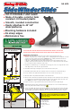
Installation Guide

R
SideWinderSlide
TM
SideWinderSlideSideWinderSlide
NE 4678
••
DO-IT-YOURSELF AND SAVE!
••
Made of durable, colorful, fade
resistant, UV-treated plastic
••
Smooth, rounded construction
••
Easily attaches to 42"-60"
slide platforms
••
Mounting hardware included
••
No sharp edges
••
Maintenance free
Swing•N•Slide Corporation guarantees every slide and climbing wall against cracking or
breaking under normal use. If either ever breaks or cracks, call us for a free replacement.
800-888-1232 800-888-1232
®
®
®
®
Lumber Requirements:
One 2" x 4" x 12' (not included)
Twelve 2-1/2'' Deck Screws
© 2010 Swing•N•Slide
1212 Barberry Drive
Janesville, WI 53545
1-800-888-1232
www.swing-n-slide.com
LA 6109
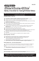
CAUTION: FAILURE TO PROPERLY SUPPORT AND
STAKE THIS SLIDE TO THE GROUND COULD RESULT IN
SERIOUS INJURY TO CHILDREN FROM LIFTING THE
END OF THE SLIDE.
Attach brace here
FIG. 3
surfacing
material
18" stake
2" below grade
FIG. 5
American Society of
Testing Materials
M
EETS OR EXCEEDS
SAFETY STANDARDS
2" x 4" x 13-1/2"
8"
12"
1
-1/2"
2
" x 4" x 13-1/2"
2" x 4" x 36"
1"
FIG. 1
T
HIS SLIDE MUST NOT BE INSTALLED OVER CONCRETE, GRAVEL, ASPHALT OR
OTHER HARD SURFACES WHICH COULD CAUSE INJURY IN THE EVENT OF A FALL
Installation Instructions
IMPORTANT: Place the slide on level ground, not less than six feet (1.8 meters) from any
structure or obstruction such as a fence, garage, house, overhanging branches, laundry lines or electri-
cal wires. Protective surfacing must extend a minimum of 6 ft. (1.828m) in all directions from the
perimeter of the equipment or from the outermost edges of any
component. A slide extending beyond the platform must have protective surfacing at least 6 ft.
(1.828m) out from both sides as well as the end. An area of 21" on either side of the slide should be
free of obstructions which a childs arm could contact.
1. Cut lumber as indicated in Fig. 1. You will require two 36" legs, two 13-1/2" cross supports and one 18''
stake. Angle the tops of the two 36" legs as indicated.
2. Assemble the slide support using three (3) 2-1/2'' Deck Screws at each joint.
3. Assemble the slide halves with a bolt, 2 washers and loc nut at each hole as indicated in Fig. 3.
4. Line up slide 90° to the platform and mark three holes 2-1/2" from the end (See Fig. 3).
5. Attach the slide to the platform with included 1'' Truss Head Screws.
6. After the slide is attached to the platform, attach the slide support to the bottom half of the slide using
one screw per side as indicated in Fig. 5. Square the support to the ground and bury the ends of the
brace. NOTE: The bottom cross support should rest firmly on the ground.
7. Prepare a level area of ground where the bottom of the slide rests 2" below grade (Fig. 4).
8. Mark where the slide’s bottom center meets the ground and drive a 2" x 4" x 18" stake until its top is
flush to the grade prepared in Step 6. (See Fig. 3)
9. Using a 1/8" drill bit, drill a pilot hole through the bottom lip of the slide and into the stake, and attach
the two using the screw provided. (See Fig. 3) NOTE: Be careful to drill into the center of the stake’s
end. Level grade around the base making sure the screw head is buried and presents no hazard.
FIG. 4
1'' Truss Head
Screw
1'' Truss Head
Screw
1'' Truss Head
Screw
2'' x 4'' x 36''
FIG. 2