ASSEMBLY INSTRUCTIONS 5′ Turbo Tube Slide Note: This accessory is designed to fit a 5′ Deck height only. C A U T I O N • Do not climb on the outside of the slide • This slide is designed for home use only, not for Public Playgrounds • Product intended for children ages from 2-10 years old. ! WARNING: Assembly by an adult. IMPORTANT!! PLEASE READ BEFORE BEGINNING ASSEMBLY!! Please make sure all lumber, hardware and accessory parts are accounted for.
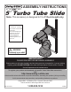
Turbo Tube Slide Dimensions 60" (152,4 cm) 64-1/2" (163,8 cm) (76 30" ,2 c m) 72" cm) ,9 (182 m imu Min Zone ty Safe 31-1/4" (79,4 cm) 90-1/2" (229,9cm) 64" m) 6c (162, 59-1/4" (150,5 cm) 2
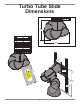
Proper Placement of Turbo Tube Slide on The Tower Option 3 ty fe Sa e e id on Sl Z NO Swing Beam Safety Zone Swing Beam y et f Sa e e id on Sl Z 47-1/2" (120,7 cm) Option 2 YES Swing Beam Safety Zone NO y fet Sa ide one Z Sl Option 1 NOTE: This diagram is based on a 47-1/2" (120,7 cm) square deck.
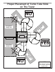
Safety Checklist for Swing-N-Slide Play Sets and Accessories Observing the following statements and warnings reduces the likelihood of serious or fatal injury Installation Safety – Have You: Consulted the assembly instructions supplied with your particular model? Noted this accessory is to be used only on Swing•N•Slide approved designs? (Do not alter its design or add/remove components.) Made sure all hardware is tightened securely? (Supplied bolt covers must also be fastened securely.
This product is intended for single family home/residential use only and not intended for use in any public setting. Placement in any public setting constitutes a misuse of this product. IMPORTANT! ADDITIONAL REQUIRED SAFETY INSTALLATION INSTRUCTIONS According to ASTM requirements, all kits must be anchored to the ground and, if the unit has a climbing rope, the rope end must be anchored to the ground. If soil conditions permit stakes to be pulled out easily, cementing into ground is necessary.
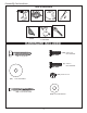
Assembly Instructions TOOLS REQUIRED CIRCULAR SAW DRILL SQUARE TAPE MEASURE SAFETY GLASSES & DUST MASK 1/2” SOCKET & WRENCH WRENCH HARDWARE INCLUDED (125) 5/16 x 7/8" Hex Head Bolt (18) 2" Lag Screw (8) 5/16 x 1" Hex Head Bolt (130) 5/16" loc nut (18) 1-1/4" Flat Washer (50) 2-1/2" Wood Screw (270) 5/16" Flat Washer 6
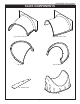
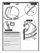
SLIDE COMPONENTS (1) Entrance Piece LH Assembly Instructions (1) Entrance Piece RH (1) Exit Elbow (9) Elbow (1) Backing Plate (1) Exit 7
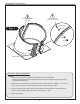
Assembly Instructions 1" Hex Head Bolts through Backing Plate 7/8" Hex Head Bolts on top seam 1" Hex Head Bolt Fig. 1 Washer Washer Loc Nut Backing Plate Entrance Section Assembly NOTES: • At least two individuals are needed to assemble the 5' Turbo Tube Slide. • To aid in aligning holes when assembling sections, insert a screwdriver through adjacent holes to maintain hole alignment. 1. Assemble the Entrance Section by securing the top seam first, as shown in (Fig. 1).
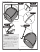
Assembly Instructions x4 Fig. 2 Fig. 2a 7/8" Hex Head Bolt Washer Washer Loc Nut Elbow Section - 9 bolts each Fig. 2b Flange Opening FLANGE DETAIL ELBOW AND EXIT SECTION ASSEMBLY 1. Assemble the Elbow Section by securing as shown in (Fig. 2) and (Fig. 2a). Join sections using a hex head bolt, two flat washers and a loc nut at each hole junction. NOTE: Fasten each loc nut finger tight. Each time you join parts be sure each flanged lip is mating with a flat lip. 2.
Assembly Instructions Fig. 3 Fig. 3a Flange Opening Fig. 3b Hex Head Bolt Washer Washer Elbow Section - 12 bolts Loc Nut Fig. 3c Fig. 3d Flange Opening Hole #1 FlANGE DETAIl Slide Elbows 1. Align the first elbow section to the Entrance Section with the seams aligned and the exit facing downward. Rotate the Elbow (2) holes to the right as shown in (Fig. 3) and secure in place. Look for the Flange Opening shown in (Fig. 3a). 2.
Assembly Instructions Fig. 4 Fig. 4a Hex Head Bolt Washer Washer Loc Nut Elbow Section - 12 bolts Fig. 4c Fig. 4b Flange Opening Hole #1 Slide Elbows 1. Align third elbow so that Hole #1 aligns with the flange opening as shown in (Fig. 4) and (Fig. 4c) and secure in place. 2. Align fourth elbow so that Hole #1 aligns with the flange opening, as shown in (Fig. 4b) and (Fig. 4c) and secure in place. NOTE: Interlocking design of flanges on Elbow pieces will assist in assembly.
Assembly Instructions Detail View Skip Hole 7/8” Hex Head Bolt Washer Foot Washer Loc Nut Skip Hole BOTTOM VIEW Exit Elbow Foot and Exit Elbow assembly 1. Take the Foot and line it up by skipping one hole down from the Exit Elbow, as shown (Detail View). 2. Attach Exit Elbow to Foot using 5/16 x 7/8" hex bolts, 5/16" washers and 5/16" loc nuts. Tighten all hardware securely.
Assembly Instructions 7/8" Hex Head Bolt Washer Washer Loc Nut Bottom section of tube slide Exit Elbow Foot Note seam locations Foot-Elbow installation 1. Install the Foot-Elbow to the bottom section of Tube assembly using (12) 5/16 x 7/8" hex bolts, 5/16" washers and 5/16" loc nuts. 2. Tighten securely.
Assembly Instructions NOTE: This plan uses a generic tower to illustrate the 5' Turbo Tube Slide being attached. However, this same procedure is to be used for any Swing-N-Slide 5’ Tower Playset. 5' DECK HEIGHT (3) 2-1/2” screws per joint 2-1/2'' screw ” ur x 4 Yo 2” h of idt oW T t Slide Barrier Construction Cu 1. Carefully remove your Barrier Support Boards from the barrier where you would like to place your slide, making certain you will have a clear 72'' Safety Zone for your slide (Fig. 6).
Assembly Instructions Fig. 7 2"x 4"x 24-1/4" (61,6 cm) 2"x 4"x 24-1/4" (61,6 cm) (4) 2-1/2'' screws per board Fig. 7a 2"x 4" 2-1/2" screw x 23" Slide Barrier Cont. 1. Install (2) 2'' x 4'' x 24-1/4'' Boards as shown in (Fig. 7) . 2. Install (2) 2'' x 4'' x 23'' Slide Support Boards on the inside of your barrier as shown in (Fig. 7a) .
Assembly Instructions (12) 2" Lag Screw (12) 1-1/4" Flat Washer Fig. 9 FLUSH (12) 2” lag screws (12) 1-1/4” flat washers FLUSH STEP 1 (2) 2” lag screws (2) 1-1/4” Flat Washers Slide Installation 1. 16 Lift and attach 5’ Turbo to units, as shown in (Fig. 9). NOTE: Two people will be required to properly align the Turbo Tube Slide with your tower.