NE 4275-4 PB 8210-4 WARNING: ! Assembly by an adult. No. of children: Up to 12 Est. building Time: 6-11 hrs. Two Adults IMPORTANT!! PLEASE READ BEFORE BEGINNING ASSEMBLY!! Please make sure all lumber, hardware and accessory parts are accounted for. If you are missing anything, please DO NOT RETURN to the store where purchased. Please call our Customer Service Department at the number below.
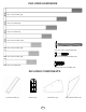
Safety Checklist for Swing-N-Slide Play Sets and Accessories Observing the following statements and warnings reduces the likelihood of serious or fatal injury Installation Safety – Have You: Consulted the assembly instructions supplied with your particular model? Noted this accessory is to be used only on Swing•N•Slide approved designs? (Do not alter its design or add/remove components, this accessory is intended for wooden playsets only, do not install on metal frame playsets).
This product is intended for single family home/residential use only and not intended for use in any public setting. Placement in any public setting constitutes a misuse of this product. IMPORTANT! ADDITIONAL REQUIRED SAFETY INSTALLATION INSTRUCTIONS According to ASTM requirements, all kits must be anchored to the ground and, if the unit has a climbing rope, the rope end must be anchored to the ground. If soil conditions permit stakes to be pulled out easily, cementing into ground is necessary.
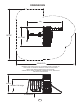
DIMENSIONS 19 28 10 10 4-7/8 30 10-1/2 MINIMUM USE ZONE FOR PLAY EQUIPMENT SHALL EXTEND NO LESS THAN 72” FROM ALL SIDES OF THE PLAY STRUCTURE. SWING USE ZONE EXTENDS NO LESS THAN 168”. SWINGS MUST HAVE A MINIMUM CLEARANCE OF 8” ABOVE THE PROTECTIVE SURFACING.
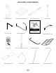
TOOLS REQUIRED DRILL 7/16’’ & 1/2” SOCKET & WRENCH PHILLIPS BIT HAMMER CARPENTER SQUARE ADJUSTABLE WRENCH SAFETY GLASSES TAPE MEASURE 1/8” DRILL BIT INCLUDED HARDWARE 30mm Deck Screw (x264) 2” Lag Screw (x24) T-20 Bit (x1) 1-1/2” Deck Screw (x58) 5/16” x 1-1/2” Lag Screw (x4) 2-1/2” Deck Screw (x513) #8 x 1/2” Pan Screw (x2) 5/16” Wood Loc Washer (x4) 3/4” Flat Head Screw (x16) #12 x 3/4” Pan Screw (x13) 8mm Loc Washer (x16) 5/16-18 Large T-Nut (x22) Weld-Nut (x16) 8mm Washer (x16) 5/16’’ L
INCLUDED HARDWARE 5/16”-18 x 7-1/2” Hex Bolt (x1) 5/16”-18 x 6” Hex Bolt (x3) 5/16”-18 x 5” Hex Bolt (x1) 5/16”-18 x 4-1/2” Hex Bolt (x13) 5/16”-18 x 3-1/2” Hex Bolt (x4) 5/16”-18 x 2-1/2” Carriage Bolt (x4) 1/4”-20 x 1-1/4” Hex Head Bolt (x16) 5/16”-18 x 3-1/4” Hex Bolt (x2) 5/16”-18 x 3” Hex Bolt (x2) 1/4”-20 x 3/4” Hex Head Bolt (x6) INCLUDED COMPONENTS Cool Wave Slide (x1) Window (x2) Beam Brace (x1) 6 Swing Beam Bracket (x2)
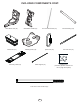
INCLUDED COMPONENTS Play Handle (x2) Beam Clamp Slotted (x6) Anchor It Strap (x4) Anchor It (x4) ‘L’ Brackets (x2) Bench Supports (x2) Plan (x1) Table Support Bars (x2) ID Tag (x1) 5/16’’ x 5-1/4’’ Swing Hanger (x6) Awning Support (x2) Awning (x2) STD Swing Seat (x2) V Hanger (x4) 22” UnCoated Chain (x4) 58” Coated Chain (x4) 7
INCLUDED COMPONENTS CONT.
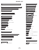
BOARD LIST (36) [PF 3430] 1’’ x 4’’ x 47-1/2’’ (1) [PF 4000] 2-5/8’’ x 6’’ x 89-1/2’’ SWING BEAM (3) [PF 3605] 1’’ x 4’’ x 44-1/2’’ (4) [PF 3441] 3’’ x 3’’ x 94’’ PLASTIC ENCAPSULATED (12) [PF 3514] 1’’ x 4’’ x 41-1/4’’ (4) [PF 4723] 3’’ x 3’’ x 78’’ (6) [PF 3523] 1’’ x 4’’ x 40’’ (1) [PF 4724] 3’’ x 3’’ x 47-1/2’’ (2) [PF 3497] 1’’ x 4’’ x 40’’ WINDOW SIDE (14) [PF 3471] 1’’ x 4’’ x 33’’ (1) [PF 3999] 2-5/8’’ x 3’’ x 62’’ SWING BEAM SUPPORT (2) [PF 3481] 1’’ x 4’’ x 33’’ WINDOW SIDE (3) [PF 3404] 2’’
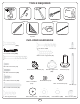
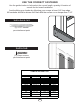
USE THE CORRECT FASTENER Use the guides below to help select the correct length, quantity & location of screws for the board installation. Avoid splitting your lumber by offsetting your screws at least 3/4” from edge.
STEP 1 CENTER ON POST CENTER ON POST 83-1/2’’ 57-1/2’’ 57-1/2’’ 45-1/2’’ 45-1/2’’ Post A Post B PF 3441 3x3x94 PLASTIC ENCAPSULATED x2 x2 1. Drill a 3/8’’ hole at the locations shown on the 3’’ x 3’’ Plastic Encapsulated Uprights as shown.
STEP 2 T-Nut Large (2) 2-1/2’’ Screw 5/16 Washer 5/16 Loc-Washer PF 3426 1x4x30 (3) 2-1/2’’ Screw per joint PF 3430 1x4x47-1/2 (3) 2-1/2’’ Screw per joint 2’’ -1/ 7 4 5/16-18 x 4-1/2’’ Hex Head Bolt PF 3426 1x4x30 (3) 2-1/2’’ Screw per joint Post A NOTE HOLE POSITIONS ON UPRIGHTS PF 4722 2x4x30 PF 4723 3x3x78 (3) 2-1/2’’ Screw (2) 2-1/2’’ Screw per joint PF 4722 2x4x30 PF 3527 1x4x28-1/2 PF 4723 3x3x78 PF 3605 1x4x44-1/2 (2) 2-1/2’’ Screw per joint (3) 2-1/2’’ Screw PF 3527 1x4x28-1/2 ’’ 30
STEP 3 T-Nut Large (2) 2-1/2’’ Screw 5/16 Washer 5/16 Loc-Washer PF 3426 1x4x30 (3) 2-1/2’’ Screw per joint PF 3430 1x4x47-1/2 (3) 2-1/2’’ Screw per joint 2’’ -1/ 7 4 5/16-18 x 4-1/2’’ Hex Head Bolt PF 3426 1x4x30 (3) 2-1/2’’ Screw per joint PF 4722 2x4x30 Post B PF 4723 3x3x78 (3) 2-1/2’’ Screw NOTE HOLE POSITIONS ON UPRIGHTS (2) 2-1/2’’ Screw per joint PF 4723 3x3x78 PF 3527 1x4x28-1/2 PF 4722 2x4x30 PF 3605 1x4x44-1/2 (2) 2-1/2’’ Screw per joint (3) 2-1/2’’ Screw PF 3527 1x4x28-1/2 ’’ 3
STEP 4 PF 4724 3x3x47-1/2 T-Nut Large 5/16-18 x 6’’ Hex Head Bolt 5/16 Washer 5/16 Loc-Washer COUNTERSUNK HOLES ON BOTTOM FLIP FRAME OVER Post B Post B Frame B 1. Attach board as shown.
STEP 5 Flush Flush (3) 2-1/2’’ Screw per joint (3) 2-1/2’’ Screw per joint Flush Flush (3) 2-1/2’’ Screw per joint (3) 2-1/2’’ Screw per joint Frame B 54” (3) 2-1/2’’ Screw per joint (8) PF 3430 1x4x47-1/2 Check to make sure structure is square 2-1/2” Deck Screw (x24) 1. Attach Support Boards to Frame B as shown.
STEP 6 (3) 2-1/2’’ Screw per joint (3) 2-1/2’’ Screw per joint Frame B (3) 2-1/2’’ Screw per joint 47 -1/ 2’’ Frame A (3) 2-1/2’’ Screw per joint Check to make sure structure is square 2-1/2” Deck Screw (x24) 1. Attach Frame A to Frame B as shown.
STEP 7 PF 3402 2x4x30 (2) PF 3514 1x4x41-1/4 (2) 2-1/2’’ Screw per joint (2) 2-1/2’’ Screw per joint PF 3402 2x4x30 (2) PF 3514 1x4x41-1/4 18 -1/ 2” (2) 2-1/2’’ Screw per joint (2) 2-1/2’’ Screw per joint 18 -1/ 2” Check to make sure structure is square 2-1/2” Deck Screw (x24) 1. Attach Deck Support Boards as shown.
STEP 8 T-Nut Large (2) 2-1/2’’ Screw 5/16 Washer 5/16 Loc-Washer 5/16-18 x 4-1/2’’ Hex Head Bolt (2) PF 4721 2x4x47-1/2 2-1/2” Deck Screw (x8) Check to make sure structure is square 1. Attach Deck Support Boards as shown.
STEP 9 18 -1/ 2” PF 3404 2x4x47-1/2 (2) PF 3514 1x4x41-1/4 (2) 2-1/2’’ Screw per joint 2-1/2” Deck Screw (x12) 1. Attach deck support boards as shown.
STEP 10 /2 7-1 4 x x4 01 3 34 PF 62-3/4” 50-3/4” PF 3426 1x4x30 (3) 2-1/2’’ Screw per joint PF 3426 1x4x30 (3) 2-1/2’’ Screw per joint 2-1/2” Deck Screw (x18) 1. Attach Barrier Support Boards as shown.
STEP 11 Flush With Top of 2’’ x 4’’ Flush With Top of 2’’ x 4’’ Flush With Top of 2’’ x 4’’ (6) PF 3514 1x4x41-1/4 (6) 2-1/2’’ Deck Screws Per Board 2-1/2” Deck Screw (x36) 1. Attach boards as shown.
STEP 12 FLUSH FLUSH FLUSH 1/4” gap typical 1/2” gap typical 1/4” gap typical (22) PF 3430 1x4x47-1/2 (6) 2-1/2’’ Deck Screws Per Board 2-1/2” Deck Screw (x132) 1. Attach boards as shown.
STEP 13 PF 3430 1x4x47-1/2 (3) 2-1/2’’ Screws per joint FLUSH FLUSH PF 3604 1x4x26 (3) 2-1/2’’ Deck Screws 2-1/2” Deck Screw (x9) (2) 1-1/2’’ Deck Screws Pre-Drill 1-1/2” Deck Screw (x2) 1. Attach boards as shown.
STEP 14 (6) PF 3426 1x4x30 (4) 30mm Deck Screws per Board 3’’ Gap Between Barrier Boards FLUSH (4) PF 3426 1x4x30 (4) 30mm Deck Screws per Board 2-1/4’’ Gap Between Barrier Boards FLUSH FLUSH 30mm Deck Screw (x40) 1. Attach boards as shown.
STEP 15 (4) PF 3426 1x4x30 (4) 30mm Deck Screws per Board FLUSH 2’’ Gap Between Barrier Boards 2’’ Gap Between Barrier Boards FLUSH (4) PF 3426 1x4x30 (4) 30mm Deck Screws per Board 30mm Deck Screw (x32) 1. Attach boards as shown.
STEP 16 COUNTERBORE HOLES ON TOP PF 4000 2-5/8x6x89-1/2 Swing Beam 5/16 T-Nut Large 5-1/4 Swing Hanger Beam Clamp Slotted 2 1 3 x6 Correct Orientation 4 (4) 30mm Deck Screws 5 1. Attach Swing Hanger(s) to swing beam as shown.
STEP 17 PF 3999 2-5/8x3x62 A-Frame SB Support 5/16”-18 x 6” Hex Head Bolt 5/16” Washer 5/16” Washer 5/16” Loc Nut (2) PF 3995 2x4x83 A-Frame 5/16”-18 x 3-1/4” Hex Head Bolt 5/16” Washer 5/16” Washer 5/16” Washer 5/16”-18 x 4-1/2” Hex Head Bolt 5/16” Loc Nut (2) 2-1/2’’ Screws 5/16” Loc Nut 5/16”-18 x 3-1/4” Hex Head Bolt (2) 2-1/2’’ Screws 5/16” Washer PF 3994 2x4x57-5/8 A-Frame Support (2) 2-1/2’’ Screws 5/16” Loc Nut 5/16” Washer 2-1/2” Deck Screw (x6) 1. Assemble A-Frame as shown.
STEP 18 (2) Swing Beam Bracket 5/16”-18 x 3-1/2” Hex Head Bolt 5/16” Washer 5/16” Loc Nut 5/16” Washer 5/16”-18 x 3-1/2” Hex Head Bolt 5/16” Washer 5/16” Washer 5/16” Loc Nut 1. Attach Swing Beam Bracket to A-Frame & Swing Beam as shown.
STEP 19 5/16”-18 x 3” Hex Head Bolt Beam Brace 5/16” Washer 5/16” Washer 5/16” Loc Nut 5/16”-18 x 7-1/2” Hex Head Bolt 5/16”-18 x 5” Hex Head Bolt 5/16” Washer 5/16” Washer 5/16” Loc Nut 1. Attach Swing Beam to tower as shown.
STEP 20 3” gap typical (6) PF 3471 1x4x33 (2) 30mm Screws per joint (2) 2-1/2’’ Screws per board 30mm Deck Screw (x24) 2-1/2” Deck Screw (x12) 1. Attach boards as shown.
STEP 21 14-3/4” PF 3430 1x4x47-1/2 (3) 2-1/2’’ Screws per joint 2-1/2” Deck Screw (x6) 1. Attach board as shown.
STEP 22 7/8’’ 7/8’’ FRONT VIEW (2) PF 3481 1x4x33 Window Side (4) 30mm Screws per board PF 3482 1x4x8-5/8 Window Top (2) 30mm Screws PF 3516 1x4x9-3/4 (2) 30mm Screws (8) PF 3471 1x4x33 (4) 30mm Screws per board 1/4’’ Gap Between Barrier Boards WINDOW FRAME (8) 3/4’’ Flat Head Screws 3/4” Flat Head Screw (x8) 30mm Deck Screw (x44) 1. Attach board(s) and Window Frame as shown.
STEP 23 PF 3420 1x3x23-1/2 (4) 30mm Screws UNDER DECK VIEW 30mm Deck Screw (x4) 1. Attach board as shown.
STEP 24 FLUSH FLUSH (13) PF 3528 1x4x24 ROCK WALL (2) PF 3404 2x4x47-1/2 ROCK WALL 2’’ Gap Bottom (3) 2-1/2’’ Screws per joint (2) 2-1/2’’ Screws per joint (2) Weld Nuts x8 Underdeck View (2) 1-1/4’’ Hex Head Bolts (1) Climbing Rock (2) 8mm Loc-Washer Per Rock (2) 8mm Flat Washer Per Rock 2-1/2” Deck Screw (x58) 1. Assemble Rock Wall as shown. 2. Mark locations of Climbing Rocks on the Climbing Wall in a pattern that will easily allow your child to climb to the deck.
STEP 25 Metal Rung (2) 2’’ Lag Screws 4-1/4” 6” PF 3603 1x4x20 (2) 2-1/2’’ Screws per joint 25-9/16” PF 3517 2x3x47 (2) 2-1/2’’ Screws per joint 20” 14-1/2” 36-1/2” (3) Metal Rungs (2) 2’’ Lag Screws per rung UNDER DECK VIEW 2-1/2” Deck Screw (x8) 2” Lag Screw (x8) 1. Attach Ladder Support Boards and Metal Rungs as shown.
STEP 26 (4) PF 3609 5/8x5x47-1/2 SHINGLE PF oo 360 f“ 8 A” 2x Fr 4x am 36 e x2 31/2 ’’ PF 4787 2x4x18-1/4 (3) 2-1/2’’ Deck Screws per joint /2 -1 32 e 4x am 2x Fr 07 A” 36 of “ PF Ro R 9” 17 -1 /2’ ’ 1x PF 4x 36 27 00 -3 /4 (2) PF 3600 1x4x27-3/4 (4) 1-1/2’’ Screws (1) 30mm Screw per shingle 1/2” (10) PF 3609 5/8x5x47-1/2 SHINGLE (3) 2-1/2’’ Deck Screws per joint (4) 1-1/2’’ Screws (1) 30mm Screw per shingle 2-1/2” Deck Screw (x24) 30mm Deck Screw (x14) 1.
STEP 27 (3) 2-1/2’’ Deck Screws per joint (2) 2-1/2’’ Deck Screws per joint Pre-Drill PF 35 27 1x 4x 28 -1/ 2 (3) 2-1/2’’ Deck Screws per joint PF 36 05 1x 4x 44 -1/ 2 28-1/2’’ PF 35 27 1x 4x 28 -1/ 2 2-1/2” Deck Screw (x14) 1. Install Safety Barrier as shown.
STEP 28 (1) Awning 1’’ FROM GROMMET CENTER (1) Awning Support (5) 3/4’’ Pan Head Screws (5) 3/16’’ Tarp Washers SLIDE BAR THROUGH POCKET IN AWNING (1) 2’’ Lag Screw per side (1) 2’’ Lag Screw per side 2” Lag Screw (x4) 3/4” Pan Screw (x5) 1. Slide Awning Support through pocket on Awning bottom as shown. 2. Attach the top of the Awning to the top board using (5) 3/4’’ screws and washers as shown. 3. Attach Awning Support to 3’’ x 3’’ uprights with (1) 2’’ Lag Screw per side. 4.
STEP 29 (2) PF 3483 5/8x4x15-3/8 (2) 30mm Deck Screw per shutter (1) Flower Box (3) 3/4’’ Pan Head Screw 30mm Deck Screw (x4) #12 x 3/4” Pan Screw (x3) 1. Install Shutters and Flower Box as shown.
STEP 30 PF 3426 1x4x30 PF 3524 1x5x29 OFFSET ARCH FLUSH 43-3/4’’ (3) 2-1/2’’ Deck Screws per joint 2-1/2” Deck Screw (x12) 1. Install Boards as shown.
STEP 31 1/2’’ Gap Between Barrier Boards PF 3498 1x4x11-1/8 Window Top (2) 30mm Deck Screw per joint (2) PF 3523 1x4x40 PF 3523 1x4x40 (2) PF 3497 1x4x40 Window Side PF 3519 1x4x14 Inside View 1-1/2’’ 30mm Deck Screw (x24) 1. Install Window Barrier as shown.
STEP 32 WINDOW FRAME (8) 3/4’’ Flat Head Screws 3/4” Flat Head Screw (x8) 1. Attach Window Frame as shown.
STEP 33 PF 3430 1x4x47-1/2 (3) 2-1/2’’ Screws per joint PF 3523 1x4x40 (2) 30mm Screws per joint 23-3/4’’ 1-1/2’’ (2) PF 3523 1x4x40 (2) 30mm Screws per joint 2-1/2” Deck Screw (x6) 30mm Deck Screw (x12) 1. Install Barrier Support Boards as shown.
STEP 34 FLUSH 1/4’’ Gap Between Barrier Boards (9) PF 3521 1x4x22-1/4 (2) 30mm Screws per joint Mount ‘L’ Brackets in the center of the Uprights 22-3/4’’ ‘L’ Brackets (2) 2’’ Lag Screws per bracket Table Support Bar 30mm Deck Screw (x36) 2” Lag Screw (x4) 1. Install Barrier Boards and Brackets as shown. 2. Install ‘L’ Brackets and Table Support Bars as shown.
STEP 35 ort pp u S ble Ta (1) 1/4-20 3/4’’ Hex Head Bolts (1) 1/4’’ Flat Washer Per Side (2) 1/4-20 3/4’’ Hex Head Bolts (2) 1/4’’ Flat Washer Per Side 1. Install Table Support and Discovery Table as shown.
STEP 36 (2) Bench Supports (2) 2’’ Lag Screws per bracket Center of Uprights PF 3981 5/4x6x47-1/2 5/16-18 2-1/2’’ Carriage Bolt (2) 5/16’’ Washer (Use washers from SA 3212 Hardware Bag) NOTE: To start Loc Nut, hold Carriage Bolt with pliers. 5/16’’ Loc Nut 2” Lag Screw (x4) 1. Install Picnic Bench as shown.
STEP 37 (1) Awning 1’’ FROM GROMMET CENTER (5) 3/4’’ Pan Head Screws (5) 3/16’’ Tarp Washers (1) Awning Support SLIDE BAR THROUGH POCKET IN AWNING (1) 2’’ Lag Screw per side (1) 2’’ Lag Screw per side 2” Lag Screw (x4) 3/4” Pan Screw (x5) 1. Slide Awning Support through pocket on Awning bottom as shown. 2. Attach the top of the Awning to the top board using (5) 3/4’’ screws and washers as shown. 3. Attach Awning Support to 3’’ x 3’’ uprights with (1) 2’’ Lag Screw per side. 4.
STEP 38 PF 3483 5/8x4x15-3/8 (2) 30mm Screws per shutter 30mm Deck Screw (x4) 1. Install Shutters as shown.
STEP 39 1-1/4’’ Lag Screws (1) Cool Wave Slide With hammer, pound stake into ground as shown. Grade PF 3419 2x4x17-1/4 Slide Stake 30mm Deck Screw (x2) (2) 30mm Deck Screws 1-1/4” Lag Screw (x3) 1. Attach slide as shown.
STEP 40 2 1 Loc-Nut x4 3 51” Un-Coated chain 5/16’’ Flat Washer QuickLink 5/16’’ Flat Washer 5/16”-18 x 6-1/2” Hex Bolt (1) Wind Rider Seat (1) Wind Rider Handle 4 QuickLink Wind-Rider 6 5 QuickLink Wind-Rider 1. Insert Seat into Handle as shown in (Step1). Secure in place with hardware shown. Note: Make certain no more than two bolt threads protrude from the Loc-Nut once fully tightened. 2. Insert (1) Quick Link into the end of each length of chain, as shown in (Step 2).
STEP 41 Swing Seat (2) 22” Uncoated chain 58” Coated chain Crimp “V” Hanger Crimp 1 x2 2 x4 3 1. Assemble Swing Seat(s) and attach to swing hangers as shown.
SWING HANGERS CRIMP NOTE: Make certain all Swing Hangers are properly seated in Beam Clamp slots. x6 1. Crimp all swing hangers closed after Swing Accessories have been attached.
ANCHOR-ITS 5/16” Washer Fold up Anchor-It Strap 5/16 x 1-1/2” Lag Screw Anchor-It x4 x4 5/16 x 1-1/2” Lag Screw (x4) 3ODFH VZLQJ VHW LQ ¿QDO ORFDWLRQ DQG PRXQW $QFKRU ,W V DW ORFDWLRQV FLUFOHG DERYH 2. Twist the Anchor-It into the ground until only the loop is exposed. 3. Place Anchor-It Strap thru loop, fold the ends together and attach to the unit as shown. Note: Keep as little play as possible using any of the holes in the strap that work best.
SAFETY HANDLES 1/4” Washer 1/4’’ x 1-3/4” Pan Screw (1) Play Handle 11” 1-3/4” Pan Screw (x4) 1.
ID TAG (1) ID Tag 1/2” Pan Screw (x2) 1. Attach ID Tag as shown.
800•888•1232 Got Questions? We’ve got answers! Call our Customer Support Representatives Available Monday - Friday, 7am - 5pm (CST) Weekend support available April through Labor Day Also available on Memorial Day, Fourth of July & Labor Day Technical Support from experienced Swing-N-Slide Customer Service Representatives who have actually built a swing set themselves.