www.swisherinc.com OWNER’S MANUAL MODEL NO. STARTING SERIAL #: L118-270001 21500 IMPORTANT Read and follow all Safety Precautions and Instructions before operating this equipment. 20 CuFt Tow Behind Feed Bin Assembly Operation Service and Adjustment Repair Parts ade I The SWISHER ACQUISITION INC.
TABLE OF CONTENTS • WARRANTY……………..…………………………………………..……………………….... 3 • SAFETY PRECAUTIONS…………………………………………..……………………….... 4 • SPECIFICATIONS …………………………………………………………………...……….. 4 • OPERATING……………………………………………………................................................ 5 – – – – – INTENDED USE ATTACHING TRAIL CUTTER TO TOW VEHICLE TRANSPORTING GENERAL RECOMMENDATIONS BEFORE EASH USE • SAFETY AND OPERATIONAL DECALS………..…………………......………..….……... 6 • ASSEMBLY PARTS…………...…………………………….....……………….….………......
LIMITED WARRANTY The manufacturer’s warranty to the original consumer purchaser is: This product is free from defects in materials and workmanship for one (1) year beginning from the date of purchase by the original consumer purchaser. We will repair or replace, at our discretion, parts found to be defective due to materials or workmanship.
SAFETY PRECAUTIONS Thank you for choosing Swisher’s 20 CuFt Feed Bin. Before operating, please read, understand and follow all of the safety precautions and other instructions explained in this manual. This Safety Alert Symbol indicates important messages in this manual. When you see this symbol, carefully read the message that follows and be alert to the possibility of personal injury. Read this manual completely.
GENERAL OPERATIONS CAUTION! Tragic accidents can occur if the operator is not alert to the presence of children. Children are often attracted to the unit and activity. Never assume that children will remain where you last saw them. INTENDED USE Your Feed Bin should be towed behind an ATV, golf cart, lawn tractor or other approved vehicle. It is not recommended for speeds exceeding 5 MPH.
SAFTEY AND OPERATIONAL DECALS Replace decal immediately if damaged. Order by part number from Swisher.
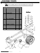
ASSEMBLY PARTS Before assembling, make sure that all assembly parts are present. ASSEMBLY PARTS Item # Description 1 Nut - Serr Flange, 1/4-20 2 Bolt - Carriage 1/4-20 X 1/2 3 Nut - Serr Flange, 3/8-16 4 Bolt - Carr 3/8-16 X 2 3/4 5 Nut - Nyloc 3/8-16 6 Bolt - 3/8-16 X 3 7 Washer - SAE Flat 3/8 8 Bolt - 3/8-16 X 3 1/2 9 Washer - 1 ID X 1 1/2 OD 10 U Bolt - 3/8-16 X 2.5 X 3 11 Ring - E-Style Retaining 12 Chain - Safety 13 Cap - 2.
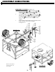
ASSEMBLY DIRECTIONS Tools Required: Wrench/Socket Qty. (2) (1) Size 9/16” 7/16” FIGURE 8.1 Use Care When Uncrating. GENERAL RECOMMENDATIONS • Use at least two people to uncrate & assemble the unit. The bin and its components are very heavy. UNCRATING See Figure 8.1 • Always wear gloves and safety glasses when disassembling the crate. • Using a hammer and pry bar, separate the boards of the crate starting with the top. Use caution to not damage the equipment inside the crate. AXLE & WHEEL See Figure 8.
ASSEMBLY DIRECTIONS HITCH See Figure 9.1 1. Loosely assemble the Hitch Tube 14 to the Axle Weldment 21 using (2) Rear Hitch Gussets 15 , (5) 3/8” X 2-3/4” Bolts 4 and (5) 3/8” Flange Nuts 3 . 2. Loosely assemble the Hitch Tube 14 to the Front Frame Tube using (2) Hitch Gussets 16 , (7) 3/8” X 2-3/4” Bolts 4 and (7) 3/8” Nuts 3 . 3. Securely tighten the hardware from the previous two steps. ɩ葆�� FIGURE 9.
ASSEMBLY DIRECTIONS JACKSTAND & COUPLER See Figure 10.1 1. Assemble the Jackstand 19 to the Hitch Tube 14 using (2) U Bolts 10 , (2) Support Plates 20 , (4) 3/8” Washers 7 and (4) 3/8” Nyloc Nuts 5 . 2. Assemble the Ball Coupler 22 to the Hitch Tube 14 using (1) 3/8” X 3 Bolt 6 , (1) 3/8” X 3-1/2 Bolt 8 , (4) 3/8” Washers 7 , (2) Safety Chains 12 and (2) 3/8” Nyloc Nuts 5 . Note the order of the parts in the diagram. 3.
PARTS DIAGRAMS COVER ASSEMBLY Item # 1 2 3 4 5 6 7 8 9 Note: Figure 11.1 depicts only the latch portion of item number 6. Description Weldment - Hopper Cover Bolt - Flat Head 5-40 X 5/8 Lid - 16" with Ring and Air Breather Handle - Pull, Aluminum Bolt - 5-40 X 3/8 Latch - Draw, Rubber Nut - Nyloc 5-40 Washer - Star Lock, #10 Bolt - Pan Head 10-32 X 1/2 Part # 21476* 21496 21475 21487 21493 21488 21494 21345 21492 FIGURE 11.
PARTS DIAGRAMS HOPPER ASSEMBLY Item # 1 2 3 4 5 6 Description Panel - Left Hopper Panel - Front Hopper Panel - Right Hopper Bolt - Carriage 1/4-20 X 1/2 Nut - Serr Flange, 1/4-20 Weldment - Rear Hopper Panel FIGURE 12.1 Ȭ襆�� Note: The holes in Item Number 6 can be used for securing a tarp or ratchet straps. Note: Some parts not shown for clarity.
PARTS DIAGRAMS TRAILER FRAME ASSEMBLY Item # 1 2 3 4 5 6 7 8 9 10 11 Description Part # Leg - Hopper Support 21457* Bolt - Carr 3/8-16 X 2 3/4 19769 Nut - Serr Flange 5/16-18 20237 Bracket - Leg Support 21473* Plug - Tubing, 2" 50062009 Bolt - Carriage 5/16-18 X .75 20236 Gusset - Corner Frame 21472* Tube - Trailer Rear 21462* Nut - Serr Flange, Hex 3/8-16 19799 Tube - Trailer Side 21459* Tube - Trailer Front 21460* ɩ鱆�� FIGURE 13.
PARTS DIAGRAMS HOPPER TO TRAILER FRAME ASSEMBLY Item # 1 2 3 4 5 6 Description Bolt - Carr 3/8-16 X 2 3/4 Nut - Serr Flange 5/16-18 Bolt - Carriage 5/16-18 X .75 Nut - Serr Flange, Hex 3/8-16 Spacer - Gate Guide Bolt - Carriage 3/8-16 X 4 Part # 19769 20237 20236 19799 21453* 21497 Ȭ镆�� FIGURE 14.1 Note: Some parts not shown for clarity.
PARTS DIAGRAMS HOPPER SUPPORT ASSEMBLY Item # 1 2 3 4 5 6 7 8 Description Bolt - 8-32 X 5/8 Bumper - Rubber Bolt - Carriage 1/4-20 X 1/2 Gusset - Hopper Support Nut - Serr Flange, 1/4-20 Bracket - Hopper Side Support Nut - Nyloc 8-32 Bracket - Hopper End Support Part # 21490 21489 21474 21454* 21485 21455* 21491 21456* Item # 9 10 11 12 13 14 15 16 17 Description Nut - Nyloc 5-40 Bolt - Carriage 1/4-20 X 1 Latch - Draw, Rubber Bolt - Carriage 5/16-18 X .
PARTS DIAGRAMS AXLE & HITCH ASSEMBLY Item # 1 2 3 4 5 6 7 8 9 10 11 Description Bolt - Carr 3/8-16 X 2 3/4 Washer - SAE Flat 3/8 Nut - Nyloc 3/8-16 Plate - Support, Jackstand Tube - Trailer Hitch Jackstand Bolt - 3/8-16 X 3 Bolt - 3/8-16 X 3 1/2 Coupler - 2" Ball Chain - Safety Gusset - Hitch Part # 19769 NB272 NB182 19477* 21461* 19179 NB150 NB649 7365 7366 21470* Item # 12 13 14 15 16 17 18 19 20 21 22 Ȭ齆�� FIGURE 16.1 Note: Some parts not shown for clarity.
GATE OPERATION ɩ둆�� FIGURE 17.1 GATE OPERATION See Figure 17.1 1. Pull the Gate Position Lock Knob outward and twist it 1/4 turn in either direction to unlock the Gate Mechanism. 2. Rotate the Gate Handle to open and close the Gate. 3. The Gate can be locked in one of the open positions or in the closed position by twisting the Gate Position Lock Knob 1/4 turn in either direction and allowing the spring loaded pin to secure the Gate.
Ȭ 18
NOTES 룠ҭ 19
www.swisherinc.com OWNER’S MANUAL MODEL NO. 21550 WHEN ORDERING PARTS, PLEASE HAVE THE FOLLOWING INFORMATION AVAILABLE: * * * * IMPORTANT Read and follow all Safety Precautions and Instructions before operating this equipment. PRODUCT – 20 CUFT FEED BIN SERIAL NUMBER - _______________ MODEL NUMBER - _______________ ENGINE MODEL NUMBER - _______________ TYPE - _______________ * PART NUMBER * PART DESCRIPTION TELEPHONE - 1-800-222-8183 FAX - 1-660-747-8650 SWISHER ACQUISITION INC.