CHANGING YOUR LANDSCAPE SINCE 1945 swisherinc.com OWNER’S MANUAL 2850 Starting Serial #: L220-324001 Plow Blade, 62" IMPORTANT Read and follow all Safety Precautions and Instructions Before Operating this Equipment.
LIMITED WARRANTY The manufacturer’s warranty to the original consumer purchaser is: This product is free from defects in materials and workmanship for a period of one (1) year from the date of purchase by the original consumer purchaser. We will repair or replace, at our discretion, parts found to be defective due to materials or workmanship.
SAFETY PRECAUTIONS This Safety Alert Symbol indicates important messages in this manual. When you see this symbol, carefully read the message that follows and be alert to the possibility of personal injury. • Read the manual. Learn to operate this machine safely. • Keep the operating speed LOW!!!!! Do not operate over 5 MPH (8 KPH). • Allow only responsible adults who are familiar with these instructions to operate this machine. Never allow children to operate this machine.
Cut Edge 2099 (13) is preinstalled to Blade 2139 (27) using 5/16-18 X 3/4 Carriage Bolt 10216 (12) and 5/16-18 Serrated Flange Nut NB170 (5).
TO ENSURE PROPER ASSEMBLY, CAREFULLY FOLLOW ALL INSTRUCTIONS LISTED BELOW Pivot Latch Assembly These steps need to be done in sequence: 1. Lay parts down in the order they are shown below. 2. Slide Plow Mount 2588 (32) into Pivot Weldment 2323 (21) and secure with ½-13 X 3½ Bolt NB577 (30) and ½-13 Nyloc Nut NB281 (18). Do not overtighten; the Plow Mount must be able to pivot freely. 3. Assemble the Pivot Latch assembly in the order shown below.
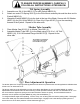
TO ENSURE PROPER ASSEMBLY, CAREFULLY FOLLOW ALL INSTRUCTIONS LISTED BELOW Pivot Mount Assembly 1. 2. 3. Connect Skid Weldment 10068 (15) through the channel on the outer right edge of the Blade using Clevis Pin NB300 (11) and Hair Pin NB127 (14) in the order shown below. Repeat for the left side. The height can be adjusted using the holes in the Skid Weldment leg.
TO ENSURE PROPER ASSEMBLY, CAREFULLY FOLLOW ALL INSTRUCTIONS LISTED BELOW Tilt Spring Assembly 1. 2. 3. Assemble one 3/8-16 Nut NB212 (7) to each Eyebolt NB635 (8). Attach one end of Tilt Spring 2335 (9) to the Plow Mount assembly tab and the other end to Eyebolt NB635 (8). Assemble Eyebolt NB635 (8) into the hole at the top of the Blade. Secure with 3/8 Washer NB272 (6) and 3/8-16 Nut NB182 (4). Place Vinyl Caps AS125 (3) over the remaining threads of the Eyebolt. Repeat for the other side.
CHANGING YOUR LANDSCAPE SINCE 1945 swisherinc.