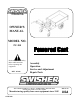
swisherinc.com OWNER’S MANUAL MODEL NO. PC-300 Powered Cart Read and follow all Safety Rules and Instructions before operating this equipment. REV. 05-108 Assembly Operation Service and Adjustment Repair Parts 1602 CORPORATE DRIVE, P.O.
LIMITED WARRANTY The manufacturer’s warranty to the original consumer purchaser is: This product is free from defects in materials and workmanship for a period of one (1) year from the date of purchase by the original consumer purchaser. We will repair or replace, at our discretion, parts found to be defective due to materials or workmanship.
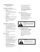
OPERATING YOUR NEW PC-300 The operation of any equipment can encounter foreign objects which could be thrown into the eyes, resulting in severe eye damage. Always wear certified safety glasses or wide-vision safety goggles over spectacles before starting machine and while operating such a machine. The operation of any engine produces sound waves that are damaging to the human ear. Ear protection is recommended. CAUTION! Tragic accidents can occur if the operator is not alert to the presence of children.
STOPPING THE ENGINE • Slide the throttle into the “STOP” position. STARTING THE ENGINE • Remove any built-up debris from engine. • Check oil & fuel. • Prime engine as directed. Note: A warm engine may not need to be primed. • Slide throttle into “FAST” position. • Pull engine coil rope. Do not pull recklessly. • Adjust throttle to desired engine RPM. For maximum results, operate in the full throttle position. PREPARING FOR FIRST USE • Check engine crankcase for oil. Check with engine dipstick.
P C -3 00 M A IN T E N A N C E & SE R V IC E B E L T A D JU S T M E N T • S top engine and rem ove spark plug w ire. • T he belt tension is adjusted by turning the cable trunnion on the idler cable located under the control panel. • P ull hairpin and rem ove w asher from cable trunnion. • P ull trunnion out of the hole in the handle. • T urn trunnion tow ard operator to increase belt tension. • Insert the trunnion into the handle. • R eplace w asher and hairpin. • R econnect spark plug w ire.
SAFETY PRECAUTIONS & DECALS This Safety Alert Symbol indicates important messages in this manual. When you see this symbol, carefully read the message that follows and be alert to the possibility of personal injury. Read this manual completely. This machine can amputate hands, feet, and throw objects. Failure to observe the following safety instructions could result in serious injury or death. • Read the manual. Learn to operate this machine safely.
PC-300 Assembly BED DETAIL PAGE 13 Frame Detail (See page 9 and 10) Console Detail (See HANDLE DETAIL PAGE 8 ENGINE DETAIL PAGE 9 FRAME DETAIL PAGES 10 & 11 FRONT/ TRANSAXLE DETAIL PAGE 14 7
Handle Detail OD117 Shift/Safety Decal for PC300 Qty (1) 10 OD99125 Medium Swisher Logo White Decal Qty (1) 11 2 8 24 23 21 17 14 16 4 19 5 22 18 4 13 9 7 24 28 29 6 7 4 25 3 31 32 15 24 30 14 34 28 25 27 12 4 33 26 27 1 SHIFT ROD/HANDLE DETAIL 20 Item 1 2 3 4 5 6 7 8 9 10 11 12 13 14 15 16 Qty 1 1 1 8 2 2 8 6 2 1 1 1 1 2 1 1 17 1 Part # Description 3311TK Bail Weldment Painted 3333TK Control Panel Weldment Painted 3334TK Handle Weldment Painted NB604 3/8 -16 X 1 GR5
Frame Detail 14 OD 71 New Serial # Decal Qty (1) OD 72 Over laminate Qty (1) 2 15 3 2 18 2 13 19 4 5 12 16 3 17 3 1 3 11 28 26 25 7 8 23 22 6 10 29 20 9 3 ITEM QTY.PART 1 1 3318TK DESCRIPTION ITEM QTY.PART Belt Dampener 15 2 3301-BC DESCRIPTION Bed Pivot Tab 2 12 NB596 5/16 -18 X 3/4 Serr Flg Bolt 16 1 NB522 1/4 X 1 Clevis Pin 3 14 NB170 5/16 - 18 Serrated Flange Nut 17 1 NB735 1/4 - 28 Yoke End ZP 4 1 See P.
Engine Detail 10 7 7 6 11 3 12 1 4 3 9 2 5 8 ITEM NO. 1 2 3 4 5 6 7 8 9 10 11 12 13 QTY. 1 1 2 1 1 1 2 1 1 1 1 1 1 PART NO. 3320 NB138 NB556 NB505 NB253 NB170 NB558 NB745 699 EBS675LS 3350EXT 3375 AS021 DESCRIPTION Belt Snubber ZP 5/16 - 18 X 2 1/2 HCC GR5 ZP 5/16 USS Flat Washer ZP 5/16 - 18 X 1 1/2 HCC GR5 ZP 5/16 - 18 X 1 1/4 Serr. Flange Bolt 5/16 - 18 Serr. Flange Nut 5/16 - 18 ZP 2 Way Lock Nut Hex Cap Screw GR5 ZP 3/8 - 24 X 2 Washer Belleville Engine Pulley Briggs 6.
Frame Detail, Bottom View 9 8 3 2 1 5 7 4 6 10 11 ITEM NO. QTY. PART NO. 1 2 NB780 2 1 3317BC 3 2 NB779 4 2 NB170 5 1 2046 6 1 3318TK 7 1 See P.
Idler Assembly 10 10 3 5 2 9 5 5 8 10 10 4 1 6 7 6 7 ITEM NO. 1 2 3 4 5 6 7 8 9 10 QTY. 1 1 1 1 3 2 2 1 1 4 PART NO. 3315TK B527 T30V NB131 NB272 NB231 NB213Z T30F NB174 NB280 DESCRIPTION PC300 Idler Idler Pulley OD - 3.
Bed Detail 6 3 8 12 5 9 1 13 4 2 OD39 7 Swisher Flag USA 11 Qty (1) 9 8 8 5 OD99112 Large Logo White Decal Qty (2) 8 4 10 14 OD116 Latch Decal for PC300 Qty (1) ITEM NO. 1 2 3 4 5 6 7 8 9 10 11 12 13 14 QTY. 1 1 1 2 2 1 1 7 5 1 1 4 4 1 PART NO. 3329C 3346Z 3336TK NB177 NB126 3325C 3312C NB272 NB182 NB618 2077 NB604 NB271 VS2 DESCRIPTION Bed Weldment Bed Pivot Axle ZP Bed Lift Handle 1/2 NR Mach Bushing 14 Ga.
Front/Transaxle Detail 17 14 15 12 9 13 3 24 9 19 7 16 20 8 1 20 2 21 6 23 3 5 4 22 6 18 5 5 11 5 10 ITEM QTY. PART NO. DESCRIPTION 1 1 3306TK 2 ITEM QTY. PART NO. DESCRIPTION Axle Weldment 13 1 3347-BC Axle Plate Outer Bolted 10 NB596 5/16 - 18 X 3/4 Serr Flg Blt 14 4 NB138 5/16 - 18 X 2 1/2 HCC GR5 ZP 3 14 NB170 5/16 - 18 Serr Flg Nut 15 4 NB275 5/16 SAE Washer 4 4 F157B Bearing Flanged 5/8 ID 1 3/8 OD 16 1 3358 Transaxle 3 Spd 5 10 NB149 5/8 ID X 1 OD 14 Ga.
Powered Cart swisherinc.com OWNER’S MANUAL Each cart has its own model number. Each engine has its own model number. The model number for the cart will be found on the frame. All cart parts listed herein may be ordered directly from Swisher Mower & Machine Co. Inc. or your nearest Swisher dealer. All engine parts may be ordered from the nearest dealer of the engine supplied with your cart. MODEL NO.