
Use and Care Guide
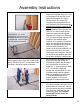
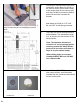
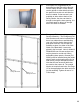

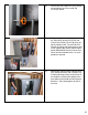
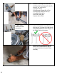
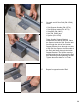
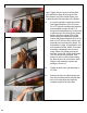
Table Of Contents
- Cover
- Warranty 1
- Warranty 2
- Warranty 3
- Operation & Safety Instructions 1
- Operation & Safety Instructions 2
- Operation & Safety Instructions 3
- Operation & Safety Instructions 4
- Operation & Safety Instructions 5
- Operation & Safety Instructions 6
- Recommended Tools For Assembly
- Anchor Bolt Alignment Templates
- Assembly Detail
- Assembly Table
- Door Assembly Detail
- Door Assembly Table
- Decals 1
- Decals 2
- Decals 3
- Concrete Slab & Anchoring Requirements
- Guidelines for Locating a Qualitfied Inspector
- Assembly Instructions 1
- Assembly Instructions 2
- Assembly Instructions 3
- Assembly Instructions 4
- Assembly Instructions 5
- Assembly Instructions 6
- Assembly Instructions 7
- Assembly Instructions 8
- Assembly Instructions 9
- Assembly Instructions 10
- Assembly Instructions 11
- Assembly Instructions 12
- Assembly Instructions 13
- Assembly Instructions 14
- Medeco Key Registration Card
- Accessory Items Also Available
- Ordering Information

黀
ǩ
15. At this point it is suggested that you
determine how the door will be brought
into the Safety Shelter. If clear access
can be gained on either side then leave
the panel for that side out until after the
door is installed. If clear access is not
available to either side or back of the
Safety Shelter, the door can later be
brought in through the door opening. It is
just much easier to bring it in through
one of the sides or the back.
16. Emergency Exit Lower and Upper Wall
Section Assembly – The Emergency Exit
Wall Sections must not be located where
there is an obstruction or wall blocking
your exit from the shelter through this
wall when removed. You do have the
flexibility to place it in either of the Side
Walls or the Back Wall. It cannot be
placed in the front wall. Note: In Model #
SR84X039G one of these sections can
only be placed on a side wall. When
assembling these panels, Gussets (PN
20063) must be installed along the inside
edge of each vertical wall section rib (as
seen at left), two per wall panel section.
Note that the two innermost bolt holes
are used on the center rib. The outside
ribs do not require these bolts. See Page
12 for the appropriate size bolts and nuts
for this assembly. Tighten all nuts to 31
Ft-lbs torque.
25
3/8-16 X 1
Carriage Bolt 19828
3/8-16 X 1 1/4
Carriage Bolt 19829