TWR10532BS, TWR10532BS-CA 10.5 HP (Briggs & Stratton) – 32” Deck SWISHER ACQUISITION INC.
LIMITED WARRANTY The manufacturer’s warranty to the original consumer purchaser is: This product is free from defects in materials and workmanship for a period of one (1) year from the date of purchase by the original consumer purchaser. As required by CFR § 1060.120, the fuel system related components, which have been certified to this equipment by SAI are to be free of defects in material and workmanship for a period of two (2) years from the date of purchase by the original consumer purchaser.
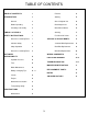
TABLE OF CONTENTS LIMIT ED W ARRANT Y 2 OPERAT ION & FEAT URES 14 T ABLE OF CONT ENT S 3 Features 14 INT RODUCT ION 4 Starting 15 General 4 Grass Height of Cut 16 Before Operating 4 Deck Adjustment 16 Uncrating & Assembly 5 Drive Wheel Detent 16 SYMBOLS & DECALS 6 Steering 17 SAFET Y INST RUCT IONS 7 Fuel Shut-Off Valves 17 General use & Safety Rules 7 SERVICE & ADJUST MENT S 18 Children Safety 8 Jackshaft Belt Replacement 18 Slope Operation 8 Deck Belt Replacement
INTRODUCTION Congratulations! Thank you for purchasing a Swisher Three Wheel Rider. This machine is built for the greatest efficiency in smaller residential settings and is perfect for saving on storage space. Innovative 360° turning drive wheel coupled with a worm style gearbox contributes to the machine’s performance and maneuverability. This manual is a valuable document. Following the instructions for use, service, maintenance, etc. can greatly increase the lifespan of your machine.
INTRODUCTION Uncrating & Assembly: Tools Required: • Tire pressure gauge • Nail bar or claw hammer • Wire snips To remove the mower from the crate: Dispose of top and side panels of the crate. Remove loose parts and packing material. Cut any banding or strapping that may be holding the mower to the crate. Disconnect the spark plug wire and place where it cannot make a connection. Raise the mower deck to its highest position.
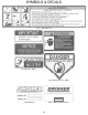
SYMBOLS & DECALS 21011 - Warning Decal Operator Must Be Seated Decal - OD73 Flying Debris Decal - OD43 Notice Do Not Alter Wiring Decal - OD74 No Step Decal - OD11 Triangle Danger Decal - OD55 Serial # ID Tag EPA / CARB Certification Decal 6
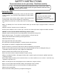
SAFETY INSTRUCTIONS These instructions are for your safety. Read them carefully. This Safety Alert Symbol indicates important messages in this manual. When you see this symbol, carefully read the message that follows and be alert to the possibility of personal injury. General Use: Read all instructions in this operator’s manual and on the machine before starting it. Ensure that you understand them and then abide by them. Learn how to use the machine and its controls safely and learn how to stop quickly.
SAFETY INSTRUCTIONS Children: Serious accidents may occur if you fail to be on guard for children in the area of the machine. Children are often attracted to the machine and mowing work. Never assume that children will stay put where you last saw them. Remember: The operator is responsible for avoiding dangers or accidents. Keep children away from the mowing area and under close supervision by another adult. WARNING Shut off the machine if children enter the work area.
SAFETY INSTRUCTIONS General Use Continued… Mowing Safety: WARNING – Gasoline is highly flammable. • Store fuel in containers specifically designed for this purpose. • Refuel outdoors only and do not smoke while refueling. • Add fuel before starting the engine. Never remove the cap of the fuel tank or add gasoline while the engine is running or when the engine is hot. Allow the engine and exhaust to completely cool down before filling.
CUSTOMER RESPONSIBILITIES Operator Presence System: Be sure to check that the operator presence and interlock systems are working properly before each use. If your mower does not function as described, repair the problem immediately. The engine should not start unless the drive pedal is disengaged, the blade lever is disengaged (forward) and the operator is in the seat. – See OPERATION FEATURES section of this manual.
CHARGING TIPS To avoid a battery explosion, never attempt to charge a frozen battery. Warning: Gel and AGM (Absorbed Glass Mat) batteries require a voltage-limited charger. Charging a Gel or AGM battery on a typical shop charger, even one time, may greatly shorten its life. Important: Never overcharge batteries. Excessive charging will shorten battery life. Prior to charging, read the manufacturer’s instructions for proper charger hook-up and use. Turn off charger prior to hookup to avoid dangerous sparks.
CUSTOMER RESPONSIBILITIES V-Belts: Check V-belts for deterioration and wear before each use and replace if necessary. Replace belts if they begin to slip from wear. SEE SPECIFICATION for belt part numbers and SERVICE section of this manual for instructions on how to replace the belt. Engine: REFER TO YOUR ENGINE OWNERS MANUAL. Overall Unit Care: Reduce the risk of fire by removing grass, leaves and other debris that may have accumulated on the machine.
CUSTOMER RESPONSIBILITIES Maintenance Schedule Before Each 8 Hours Use Check Brake Pad Operation X Check Tire Pressure X Check Operator Presence X Check for Loose Fasteners X 25 Hours 50 Hours 100 Hours Season Before Storage X X X X Sharpen/Replace Mower Blades X3 Check Battery X X Clean Battery & Terminals X X Check Belts X Check Engine Oil X X Change Engine Oil w/ filter Change Engine Oil w/o filter X1,2 X1,2 Replace Oil Filter Clean Air Filter X1,2 X2 Inspect Muffler X
OPERATION & FEATURES 4 6 8 14 9 5 10 1 7 2 11 12 13 1. Steering Wheel – Used to control the direction of the machine. 2. Tiltable Steering Wheel Adjustment 3. Blade Engage Lever – Used to engage or disengage the deck blades. 4. Ignition Switch – Used to start or stop the engine. 5. 6. 3 Deck Lift adjustment – Used to raise and lower the cutting deck. Drive Pedal – Sets the speed of the mower (in both forward and reverse directions). 14 7. Fuel Tank – 2 Qt. 8. Battery 9.
OPERATION & FEATURES 2 1 3 4 KEY SWITCH 1. Power Off position 2. Mow-in-reverse position – will NOT shut off engine when mowing in a generally rearward direction. 3. Engine Run position – Engine WILL shut off if mowing in a generally rearward direction. 4. Engine Start position NOTE: If you have never used a tractor or zero turn mower before, refer to the Operation Controls section of this manual before attempting to operate one for the first time.
OPERATION Grass Height & Cutting Suggestions: Do not attempt to cut wet grass. The average lawn should be cut to 2 ½” during the cool season and to over 3” during the hot months. For healthier and better looking lawns, mow often and after moderate growth. As a rule, never cut more than 1/3 of the total grass blade length. Correct mowing height can reduce weeds and lawn disease. For best performance, grass over 6 inches in height should be mowed twice.
OPERATION Steering Be familiar with all steering, its function and how to operate the machine before beginning to operate. The drive wheel turns 360° but the steering wheel is a 2:1 ratio to the drive wheel. This means for every two turns of the steering wheel the drive wheel will turn one complete revolution (360°). IMPORTANT: Always be aware of which direction the drive wheel is facing before engaging the drive pedal.
SERVICE & ADJUSTMENTS Jackshaft Belt Routing & Replacement For replacement belt part number refer to Replacement Parts Quick Reference Chart in this manual. Removal Disconnect spark plug wire. Make sure machine is on level ground. Jack up the front of the machine to gain access to the belt. Release the tension from the idler. Roll the belt over the top of the jackshaft pulley. 1. Engine-to-Jackshaft belt 2. Engine pulley 3. Jackshaft pulley 4. Inside idler pulley 5.
SERVICE & ADJUSTMENTS Deck Belt Routing & Replacement For replacement belt part number refer to Replacement Parts Quick Reference Chart in this manual. Removal 1. Engine-to-Deck belt 2. Deck pulleys 3. Engine pulley 4. Backside deck idler 5. Idler tension spring 6. Brake pads Disconnect spark plug wire. Make sure machine is on level ground Disengage the deck engagement lever. Remove the belt covers. Roll the belt over the top of the deck pulleys then the engine pulley.
SERVICE & ADJUSTMENTS Drive Belt Routing & Replacement For replacement belt part number refer to Replacement Parts Quick Reference Chart in this manual. Removal Disconnect spark plug wire. Make sure machine is on level ground. Remove hood. Make sure the drive pedal is disengaged. Remove belt from the drive and jackshaft pulleys. If the belt tension is too tight to remove, one of the pulleys may need to be removed as well. 1. 2. 3. 4. 5. 6. 7.
WIRING HARNESS WIRING HARNESS P/N 20858 21
PARTS BREAKDOWN 22
PARTS BREAKDOWN I TEM # 1 2 3 4 5 6 7 8 9 10 11 12 13 14 15 16 17 18 19 20 21 22 23 24 25 26 27 28 29 30 PART # 20709* 20717 T30V 009X42 NB280 6037 10216 NB121 NB177 H7N N/A 20766* 20794* 4578* 10548 11158 NB164 NB272 NB207 20783* 2077 NB170 3609 20808* 26X249 20057 NB221 NB271 NB252 18580 DESCRI PTI ON Weldment - Main Frame Ride King Tire/Wheel - 11 x 4.00 - 4, Turf Tread Pulley - I dler Clutch, 2 3/4 OD Bolt - Shd. 38-16X.
PARTS BREAKDOWN 24
PARTS BREAKDOWN ITEM # 1 2 3 4 5 6 7 8 9 10 11 12 13 14 15 16 17 18 19 20 21 22 23 24 25 26 27 28 29 30 31 32 33 34 35 36 37 38 39 40 41 42 43 44 PART # 20709* A124B 20716* T30V 20843* 20860 009X42 NB280 20861Z 20802Z 20862 20735* 12394 20732* 20745* 20751Z 20750Z NB263 NB264 20752 20753 20746 6037 10177 20757* 20759* 20760* 10216 10548 NB164 NB272 NB207 NB102 20294 NB170 13182 NB134 B27 26X249 NB221 NB275 NB181 NB596 19035 DESCRIPTION Weldment - Main Frame Ride King Bushing - Flanged (Up/Low) Ea.
PARTS BREAKDOWN 26
PARTS BREAKDOWN ITEM # 1 2 3 4 5 6 7 8 9 10 11 12 13 14 15 16 17 18 19 20 21 22 23 24 25 26 27 28 29 30 31 32 33 34 35 36 37 38 PART # 20739* 19924* B98 B4104* 20740 20741 NB280 7509 6037 10216 4005 NB604 NB177 10038 20776Z B98W NB179 NB175 20771Z 20768* 20767Z 056054 AS001 20774 20777 NB607 AS155 20778Z 20779* 4422 NB260 NB164 NB272 NB182 NB207 20784* 19297* 20787* DESCRIPTION Weldment - 32" Deck Housing - Cast Iron Blade Driver Bearing Pulley - Blade 4 1/2" Blade - 17.5" Flat, High Lift Blade - 15.
PARTS BREAKDOWN 28
PARTS BREAKDOWN ITEM # 1 2 3 4 5 6 7 8 9 10 11 12 13 14 15 16 17 18 19 20 21 22 23 24 25 26 27 28 29 30 31 32 33 34 35 36 PART # 20797Z AS010 TR150W NB156 NB121 NB275 NB503 NB181 NB177 20799* NB524 10547 AS165 NB641 20848 20866* 20713* 20712* NB280 NB130 20832 20819Z 20816Z 20817Z 20798Z 12473 20835 20836Z NB620 14399 20840Z 20710 TR148PW TR148S 20839Z NB126 DESCRIPTION Weldment - Drive Sprocket/Hub ZP Bearing - (1) 1616ZZ (TR150, T137) Washer - .531IDX1 1/2ODX.
PARTS BREAKDOWN ITEM # 1 2 3 4 5 6 7 8 9 10 11 12 PART # 20718 NB170 N/A NB254 NB710 NB172 699 NB452N 9031 20831 20871 20872 DESCRIPTION Pulley - Stacked, Engine to Deck Nut - Serr Flange 5/16-18 ZY Case Hrd Engine - B&S 10.5 HP Nut - Serr Flange, 1/4-20 Grade 5 ZY Screw - 10-24 X 1 1/2 MSC Unslot Hex ZY Nut - Kep 10-24 ZY Washer - Bellev ille 7/16 X 1 1/4 Bolt - 7/16-20 X 1 HCF GR5 ZP Nyloc Key Stock - 1/4 X 1 Undr Sz Plain Fin Muffler - Briggs, 10.
TROUBLESHOOTING PROBLEM Engine Will Not Start Engine Hard To Start Engine Will Not Turn Over Engine Clicks but Will Not Start Excessive Vibration CAUSE CORRECTION 1. Out of fuel. 1. Fill fuel tank. 2. Engine flooded. 2. 3. Bad spark plug. Wait several minutes before attempting to restart. 4. Dirty air filter. 3. Replace spark plug. 5. Dirty fuel filter. 4. Clean or replace air filter. 5. Replace fuel filter. 6.
TROUBLESHOOTING PROBLEM Loss of CAUSE CORRECTION 1. Cutting too much grass / too fast. 1. Raise deck height / reduce speed. 2. Buildup of grass, leaves and trash under deck. 2. Clean underside of mower deck. 3. Clean or replace air filter. 4. Check oil level/change oil. 5. Clean and re-gap or change plug. 6. Replace fuel filter. 7. Drain fuel tank & refill tank with fresh gas. 8. Drain fuel tank & carburetor, refill tank with fresh gas and replace fuel filter. Power 3.
MOWER IDENTIFICATION Mower Identification Unauthorized Replacement Parts Each mower has its own model number. Each engine has its own model number. The model number for the mower will be found behind the seat. The model number for the engine will be found on the top of the blower fan housing. All mower parts listed herein may be ordered directly from Swisher or your nearest Swisher dealer. All engine parts may be ordered from the nearest dealer of the engine supplied with your mower.
REPLACEMENT PARTS Quick Reference Swisher Part # 20846 37X129 Part Description Belt - Wrapped, 34.5" Belt - 30" Drive 18638 Belt – Deck Idler, ½ x 54 20710 Tire & Wheel - 4.10/3.50-5 w/ Pin Drive 20717 Tire/Wheel - 11 x 4.00 - 4, Turf Tread 20848 Chain - Roller, 77 Link Loop 20740 Blade - 17.5" Flat, High Lift 20741 Blade - 15.5" Flat, High Lift AS069 Fuse – 10 Amp 19924TK 20774 B98 Housing - Cast Iron Blade Driver; Txt Blk Shaft - Blade Driver, 5.635 Bearing - Blade 056054 Pad - Brake 1.
SWISHER HISTORY Back before electricity came to rural Missouri Max Swisher was producing lawn mowers from his mother’s chicken house. Max never liked to mow grass. He installed a gearbox on his family’s lawn mower creating a self-propelled unit. By tying one end of a rope to the mower and the other end to a tree in the center of the yard the mower circled the tree, shortening the rope and guiding the mower in concentric circles. Max enjoyed relaxing under a shade tree while his invention did all the work.