f swisherinc.com OWNER'S MANUAL ? MODEL NO. ZT1436B ZT18542 ZT2250 "Z"SERIES IMPORTANT Read and follow all SafeR" Precautions and Instructions before operating equipment. Operation Service and Adjustment J ( Manufacturing ONZTR04 Assembly this Rev. 06-039 1602 CORPORATE ZERO TURNHYDROSTATIC DRIVE Repair Parts DRIVE, P.O.
LIMITED WARRANTY The manufacturer's warranty to the original consumer purchaser is: This product is free from defects in materials and workmanship for a period of two (2) years from the date of purchase by the original consumer purchaser. We will repair or replace, at our discretion, parts found to be defective due to materials or workmanship.
Thank you for choosing Swisher's Zero Turn Rider Mower. Before operating your mower, please read, understand and follow all of the safety precautions and other instructions equipment, lawnmowers explained can be potentially in this manual. dangerous As with all power if improperly used. J SAFETY This PRECAUTIONS Safety manual. follows Read objects. Failure serious injury or death. • • • • • • • When and completely.
The operation of any cutter can encounter foreign objects to be thrown into the eyes, resulting in severe eye damage. Always wear certified safety glasses or wide-vision safety goggles for over spectacles before starting any cutting machine and while operating such a machine. I0 The operation of any cutter produces sound waves that are damaging human ear. Ear protection is recommended. to the CAUTION! Tragic accidents can occur if the operator is not alert to the presence of children.
• • • • • • • • • • • • Turn off the bladeswhennot mowing. Beforeleavingthe machine,turn off theblades andstopthe engine. Watchfor traffic whenoperatingnearor crossingroadways. Do not operatethe mowerif it hasbeendroppedor damagedin anymanneror if the mowervibratesexcessively.Excessivevibrationis anindication of damage. Repairmowerasnecessary. Dressproperly. Do not operatethe mowerwhen barefootor wearingopensandals. Wear only solid shoeswith goodtractionwhenmowing.
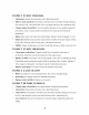
Danger/WarningDecal- OD99155 Ignition/PTO/ThrottleDecal- OD99154 Ignition!PTO/ThrottleDecal 50" Mower Only - OD99157 SwisherFlagU.S.A.- OD39 Notice Do Not Alter Wiring Decal- OD74 TriangleDangerDecal- OD55 Operator Must Be Seated Decal- OD73 Parki g BrakeDecal- OD99152 ............................................... __ _ Flying Debris Decal- OD43 No Step Decal - OD11 DECALS NOT SHOWN Swisher Z 18.5/42" Decal-Left- Z 14.5/36" Decal- OD112 OD124 36" Deck White Decal- OD99159 Z 22.
UNCRATING/ASSEMBLY • • • • • • • • • • • • • • Dispose of top and side panels of the crate. Remove loose parts and packing material. Cut any banding or strapping that may be holding the mower to the crate. Disengage spark plug wire and place where it cannot make a connection. Assemble the seat and clip wiring harness into the bottom of seat. NOTICE: Mower will not start unless the seat is connected to the wiring harness. Raise mower deck to its highest position by turning the handle clockwise.
MOWING WARNING: Do not operate moweraccidents at too fast of a rate. backward at fast speeds can cause resulting in Sudden personal movements iniury. forward and • Start out moving steering levers SLOWLY forward and backward until you learn to operate the unit. NOTE: This mower has been designed to be very maneuverable. Practice in open, flat areas is extremely necessary to become comfortable and efficient with the controls. • BEGIN • Start the mower engine.
MAINTENANCE INSPECT BEFORE Loose fasteners: blades. Parking brake: repaired. EACH SCHEDULE USE Be sure all fasteners are at proper torque. Especially guards and If brake does not keep unit from rolling, brake must be adjusted or Tires: Always check and maintain proper tire pressure (See tire sidewall for recommendation). Check for damage due to sharp rocks, objects or stumps.
INSPECT EVERY • Lubrication: • Battery, Grease check will extend • Change 25 HOURS all pivot and clean: its life. Clean engine instructions. oil and Select points Keep battery terminals filter: viscosity with a high telnp terminals with a wire grade according clean brush Use only quality grease. and tight. Periodic charging and coat with a petroleum detergent to your oil. See engine expected jelly. manual for environmental temperature.
SERVICE ,_ CAUTION: / ADJUSTMENTS Before performing any service or adjustments do as follows: 1. Turn off PTO switch. 2. Position unit on smooth flat surface. 3. Place steering levers in outward, neutral-locked position. 4. Turn ignition key "OFF" and set parking brake. 5. Wait for all moving parts to stop and disconnect spark plug wire. TRACKING Adjustments to the unit may need to be made if the unit does not track in a straight line.
REMOVING . THE MOWER DECK Turn off engine and engage parking brake. 2. Rotate cutting height lever counterclockwise 3. Remove 4. Remove cotter pins on rear hanger points and slide out stabilizer tension spring bolt from tension bracket. . 6. Remove to lowest cutting position. bolt from pickup point located at the front of the deck. bars.Disconnect belt from mower pulley and electric clutch. Slide mower deck from under unit. INSTALLING THE MOWER DECK 1. 2.
LEVELING THE MOWER 1. unit on a smooth level surface. . . Position DECK For side to side leveling, measure the distance from the floor to the bottom edge at the rear of the deck. The measurement should be equal within 1/16 inch side to side. Adjustment can be made by loosening locking nut on rear eyebolt hangers and adjusting up or down as needed. For front to rear pitch adjustment, loosen locking nut on front eyebolt and adjust up or down as needed.
: BELTS 50" Clutch drive belt replacement 1. Remove belt covers. 2. Disconnect bracket. Part #: 3816 3. Remove clutch. tension idler from tension belt from mower pulley and electric 4. Install new belt onto electric clutch and mower pulley and check for proper routing and clearance. 5. Reconnect idler tension bolt to tension ,/ bracket. 42" Part #: 3752 Hydrostats belt replacement 1. Remove clutch drive belt. See clutch belt replacement. 2. Disconnect wiring from electric clutch. 3.
WIRING DIAGRAMS 36" and 42" Mowers / 15
ENGINE Item # SETUP Description 14 HP B&S Engine (36" Mower) 18.5 HP B&S Engine (42" Mower) 22 HP B&S Engine (50" Mower) 5/16-18 Serrated Flange Nut Spacer Engine Pulley Motor Pulley 3" 1/4 X 1/2 Key Stock Engine Pulley Spacer Short .687 Part # N/A N/A N/A NB170 BB105SL 3753 4258 689S 8 9 Electric Clutch Drop Pulley Electric Clutch (50" Mower Only) Washer Belleville Engine Pulley 7/16-20 X 3.
Item # 1 2 3* 4 5 6 7 8 9 10 11 12 13 16" 17 18 19 2O 21" 22* 23 24 Transaxle Right Part# BRS6H 682S NB170 NB501 3690TK NB131 NB107 NB272 B27 NB280 NBl18 NB181 3678TK 3825 2203LN 3755 3604 3756 3601CB 3600CB Belt Snubber (50" Only) 5/16-18 X 3/4 Serr FIg Bolt 1/2-13 Nyloc Nut 5/16-18 ZP 2 Way Lock Nut 3819TK NB596 NB281 NB558 Description Wire Link For Idler Arm Clutch Rod Spring 5/16-18 Serrated Flange Nut 5/16-18 X 1 HCC GR5ZP Transmission Idler Arm 1/2-13 X 3 HCC GR5 Bolt ZP 3/8-16 X 1 1/2 HCC GR5ZP
STEERING (RIGHT SIDE SHOWN) 24 21 2O /4 26 18 17 3 28 33 6 / Item # 1 2 Description Directional Handle Grip Right Handle-Weldment Left Handle-Weldment 3 4 5 6 7 5/16-18 X 3/4 Serr Fig Bolt 5/16-18 Serrated Flange Nut 1/2 NR Mach Bushing 14 GA 1/2 ID X 7/80D X 1/8 N_on Washer Right Handle Mount Weldment Left Handle Mount Weldment Pivot Plate Right Weldment Pivot Plate Left Weldment 9 10 11 12 13 14 15 16 17 1/2-13 Nyloc Jam Nut 1/2-13 2-Way Jam Lock Nut Washer 1/2-13 X 2 1/2 HCC GR5ZP 1/4 Ro
SEAT BASE ASSEMBLY Item # I 2 Description Only) 3790 Seat 15" Back With Arm Rest (42" Mower Only) 3791 Seat 18" Back With Arm Rest (50" Mower Seat Plate Only) 3792 3133TK 3 5/16-18 4 Shoulder Bolt NB743 Seat Bracket 5 5/16-18 6 Tinnerman 7 8 Part # Seat 15" Back No Arm Rest (36" Mower 5/16-18 3833TK Nyloc Nut NB181 Clip 5/16-18 3706 X 3/4 Serr Fig Bolt NB596 9 5/16 ID X 1 1/40D 11GA Black N_on Washer 5/16-18 Jam Nut NBl16 NB173 10 T Knob 5/16-18 3844 11 Control Cover C
PARKING BRAKE Item # 1 2 3 4 5 6 7 8 9 10 11 12 13 14 15 16 17 18 19 2O 9 j! / l l0 12 13 15 ld 14 42" & 50" Mowers 5/16-18 X 1 Eye Bolt 5/16-18 Serrated Flange Nut Spring (2 speed) Parking Brake Weldment T Knob 5/16-18 5/16-18 Jam Nut Part # 3267TK NB126 3390Z NB181 NB558 NB556 NB202 NB170 T2SM 3797TK 3844 NB173 5/16 11GA Black Nylon Washer 1/4-28 X 3/4 GR5 ZP NBl16 NB620 1/4 Split Lock Washer 5/16 X 1 1/40D Fender Washer E-Brake Handle E-Brake Side link 5/16-18 X 1 1/2 GR5 Bolt 5/16-18 X 1 G
FRAME for 36" Mower 5 3 6 /5 \ 7 \ 10 ll 25 23 2 \ 12 SEE DETAIL \ 9 @ 33 31 12 18 22 32 15 24 39-- 17 19 36 Item # 1 2 3 4 Description Beverage Retainer 5/16-18 X 1/2 Serr.
FRAME for 42" Mower 2 31 [j33 \\ 4 .
FRAME for 50" Mower 35 28 13 15 13 ,2 / SEE DETAIL 18 PAGE 17 19 & 20 24--.
DECK l LIFT \ Item # 1 Description Plastic Knob - Black Part # 4857 2 3 4 3/8-16 2-Way Lock Nut 5/18 USS Fiat Washer ZP 3/8-16 X 1 1/4 GR5 ZP NB280 NB558 NB618 5 6 7 8 9 10 11 12 Spacer 3/40D X .515 tD DOM X 1.
BLADE DRIVER BLADEDRIVER For 36" Mowers For 42 and 50" Mowers 2 2O 2O d 7 11 _o 5 ll 12 4 12 17 14 12 14 8 _13 13 Item # 1 2 3 4 5 6 7 8 / Description 3/4-16 2 Way Lock Nut 1.5x.761 x.098x.134 Belleville Washer Blade 15 / ld Pulley- 5.5" (42" Mower Only) Washer For Blade Driver Blade Bearing Blade Shaft 4.
36" MOWING DECK 3 5 6 7 / 10 11 21 6 8 SEE DETAIL SEE DETAIL Page 16 THIS PAGE 12 Item # 1 2 3 4 5 6 7 8 9 13 15 14 NOT SHOWN Roller Bracket (12) Mounting Hardware DESCRIPTION PART # QTY 5/16-18 X 3/4 SerrFIg Bolt NB596 ....... 2..........
42" MOWING DECK _3 @ 9 l0 ll 15 14" Item # 1 2 3 4 5 6 7 8 9 NOT SHOWN Roller Bracket (12) Mounting DESCRIPTION Hardware PART # 5/16-18 X 3/4 Serr Fig Bolt NB596 5/16-18 Serrated Flange Nut NB170 QTY 2 2 DECK IDLER 10 11 12 13 14 15 16 17 18 19 20 21 22 23 24 25 26 27 28 29 30 28 24 23 29 27 Description Grass Chute Weldment Grass Chute Mount 5/16-18 X 8 1/2 HCC GR2 ZP Torsion Spring - Bent Leg Deck Weldement 5/16-18 X 3/4 Serr Fig Bolt Pulley Cover 5/16-18 Serrated Flange Nut Sway Bar Left
5 0" MOWING DECK 14 6 10 20 SEE DETAIL THIS PAGE 1! ld Page 16 12 15 Pa_ DECK IDLER _d# 3 14 4 5 6 37 Grass Description Chute Weldment 5/16-16 X 3/4 Serr Fig Bolt Grass Chute Mount 5/16-18 7 8 26 23 / "_ 22 :8 3/8-16 4 27 5/16-18 X 4 Carriage Bolt Anti-Scalp Roller 3/8-16 2-Way Lock Nut 3/8-16 X 5 1/2 GR5 ZP Sway Bar-Right Sway Bar-Left Deck Weldment 5/16-18 5/16-18 Serrated Flange Nut X 8 1/2 HCC GR2 ZP 20 21 22 Torsion Spring 3/8-16 HNC GR2 ZP 3/8 SAE Washer 23 24 25 26 27 28 I
TROUBLESHOOTING SYMPTOM ENGINE TO CAUSE HARD START CORRECTION i. WEAK OR DEAD 2. AIR FILTER DIRTY 2. CLEAN 3. BAD PLUG 3. REPLACE SPARK 4. FUEL 4. REPLACE FUEL 5. STALE 5. DRAIN AND REPLACE FRESH FUEL SPARK FILTER OR CONTAMINATED NOT START OR LOSS OF 2. PTO SWITCH 3. THROTTLE POWER ENGINE NOT IN NEUTRAL IS ENGAGED NOT SET PROPERLY NOT PROPERLY 4. FUEL OR REPLACE OR RECHARGE OR REPLACE CONTACT OUT OF AD,RJSTMENT STEERING LEVERS LOCKED POSITION WILL i.
SUGGESTED GUIDE FOR S_ONT_NG SLO ES FOR SAFE OPERATION
WARRANTY YOUR WARRANTY RIGHTS AND OBLIGATIONS: RIGHTS AND OBLIGATIONS The California Air Resources Board and Swisher Mower, is pleased to explain the evaporative emission control system (EECS) on your model year 2006 and later Swisher Product. In California, new Outdoor Power Equipment, must be designed, built and equipped to meet the State's stringent anti-smog standards. Swisher Mower must warrant the EECS on your Power improper maintenance.
f -'x f "Z"SERIES swisherinc.com ZERO TURNHYDROSTATIC DRIVE Each mower has its own model number. Each engine has its own model number. The model number for the mower will be found under the seat. The model number for the engine will be found on the top of the blower tan housing. All mower parts listed herein may be ordered directly from Swisher Mower & Machine Co. Inc. or your nearest Swisher dealer.