XMT-120A / XMT-350 DMX Measurement Tool / Tester USER MANUAL
Revisions History Revision Description Date First Draft 23.08.12 1.1 Draft English XMT-120A and XMT-350 (ler) 09.10.12 1.3 Edited (boc) 22.03.
Table of contents 1 Introduction......................................................................................................................................................................4 2 Applications.......................................................................................................................................................................4 3 Typical Application............................................................................................................
22.2 Ground Topologies...............................................................................................................................................23 23 Safety Information........................................................................................................................................................24 24 Technical Data.......................................................................................................................................................
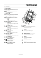
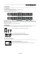
Overview 1 2 3 4 5 6 7 8 9 10 11 (func) (toggle) BACKLIGHT With this button the backlight can be switched on or off POWER With this button the device can be switched on or off OK [OK] Choose a menu point with this button Enter special settings Enter the special settings menu Cancel [CANCEL] Escape from a menu point with this button Toggle Toggle values in send mode CHANNEL + [RIGHT] Increase the DMX channel (address) NAVITGATE Use to navigate to the right in the user menu CHANNEL - [LEFT] Dec
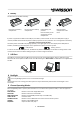
Battery The XMT uses a 9 volt alkaline battery. 4 3 2 5 1 Lift to open the battery compartment. Pull to remove the battery compartment. Check battery pole positions. Push the battery on the spring down into the compartment. Push the battery compartment to the touch. If power is supplied to the XMT via the USB port, the battery is disconnected. As soon as the USB power supply is removed, the XMT will automatically switch to battery operation.
FIXTURE Configure fixtures and patch them. OPTIONS Options of the XMT. CONNECT TO PC Mode to connect the XMT to the PC software. On the XMT-120A: Select the desired mode by using the navigation buttons [CH+] and [CH-]. Press [OK] to confirm the selection or [CANCEL] to return to the previous mode. On the XMT-350: Select the desired mode by using the navigation buttons [CH+], [CH-], [+] and [-]. Press [OK] to confirm the selection. 10 RECEIVE DMX Press the [MODE] button and choose RECEIVE DMX.
In receive mode, the received signal will be amplified and sent to the DMX out port. This allows you to connect the XMT in the middle of the DMX line and the signal will be terminated at the DMX in port of the XMT. 11 Receiver Options When the XMT is in receive mode, press the [OK] button to enter the special settings menu. STORE SCENE Create a snapshot of the incoming DMX data and store the values to a scene. SHOW LEVEL AS Choose whether the level is displayed in percents, decimal or hexadecimal.
11.4 ADDRESSES In receive DMX mode: • Press [OK] to access the receiver options. • Choose the ADDRESSES item with the [UP] and the [DOWN] buttons. • Press [OK] to change the address access mode. • Press [Cancel] to exit the receiver options.
12.2 Set Level of Group of Channels (LED) Use [CH+] and [CH-] buttons to select a group of channels. All groups are located below the channel 1. Use the [+], [-], [0%], [50%] and the [100%] buttons to set the level of a group of channels. The available groups are shown below.
• Choose a scene with [UP] and [DOWN] buttons. • Press [OK] to confirm. • Press [CANCEL] twice to exit the send options. Note: The scenes in receive DMX mode and in send DMX mode are shared. All 512 channels are stored into a scene. Storing to a scene overwrites the scene's previous content. The scenes can be combined to a sequence by using the sequence editor. See chapter SEQUENCE.
13.3 LOAD SCENE In send DMX mode: • Press [OK] to access the send options. • Choose LOAD SCENE with [UP] and [DOWN] buttons. • Press [OK] to access the list of scenes. • Choose the scene with [UP] and [DOWN] buttons. • Press [OK] to confirm. • Press [CANCEL] twice to exit the send options. All 512 channels of the scene are loaded. 13.4 SHOW LEVEL AS In send DMX mode: • Press [OK] to access the send options. • Choose the SHOW LEVEL AS item with the [UP] or with the [DOWN] button.
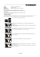
NORMAL MODE DIRECT MODE (toggle) S S S 13.6 REFRESH RATE In send DMX mode: • Press [OK] to access the send options. • Choose the REFRESH RATE item with the [UP]/[DOWN] buttons. • Press [OK] to change the refresh rate. • Press [Cancel] to exit the send options. Available refresh rates are: 5, 10, 15, 20, 25, 30, 35, 40, 44 Hz (frames/sec). 14 CABLE TESTER Press the [MODE] button and choose CABLE TESTER. Now, press the [OK] button to enter the cable tester mode.
Connect a DMX source to the XMT's DMX in port. The level of one channel is traced. The address of the current channel is displayed on the bottom left of the screen. Use [CH+] and [CH-] buttons to change that address. Use the [Cancel] button to stop and resume the tracing. When stopped a small cursor appears. The position of the cursor is displayed on the bottom right of the screen.
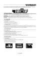
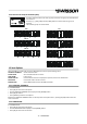
16 TIMINGS Press the [MODE] button and choose TIMINGS. Now, press the [OK] button to enter the timings mode. Connect a DMX source to the XMT's DMX in port. AF TE ST R AR BR TC EA O K DE CH A NN EL 1 CH AN NE L2 CH A NN EL 3 CH A NN EL 4 M AR K A K BR E CH AN NE L5 CH 11 AN NE L5 12 The XMT shows basic DMX-512 timings. DMX SIGNAL Shows if a DMX signal is OK or faulty. REFRESH RATE Shows the numbers of frames received per second. BREAK LENGHT Shows the length of the break in microseconds.
17.1 EDIT SEQUENCE • Choose the EDIT SEQUENCE item with [UP]/[DOWN] buttons. • Press [OK] to enter the sequence editor. The sequence can be created with up to 100 steps using 32 scenes. The scenes can be recorded in receive and send mode. Choose a step with the [CH+] and [CH-] buttons. For each step, choose a scene with the [+] and [-] button. Set the end of the sequence by choosing scene 0 (will be displayed as “end”).
ID The fixture ID. It will be incremented automatically. FIXTURE Name of the fixture type. ADDRESS The patch address for the fixture. The XMT proposes the next free DMX address as the patch address. This address can be changed with the [CH+] and [CH-] buttons. • Press [OK] to patch the device. If a fixture is patched, the receive DMX mode and the send DMX mode will show information about the current channel on the bottom of the screen. Parameter Description Fixture Name Fixture ID 18.
19 Connect to PC The XMT PC Software can be downloaded from the Swisson website. www.swisson.com • Install the XMT PC Software before connecting the XMT to the PC. • Connect the XMT to the PC with a USB cable. • Press the [MODE] button and choose PC Connection. Press now the [OK] button to enter the PC connection mode. PC XMT-120A / XMT-350 20 OPTIONS Press the [MODE] button and choose OPTIONS. Now, press the [OK] button to enter the options menu. The options menu has following items.
If enabled, the binary representation of the address is displayed below the address in receive DMX mode and in send DMX mode. BinaryAddress 20.4 Show Min and Max Values • Choose the SHOW MIN-MAX item with [UP] or [DOWN] buttons. • Press [OK] to toggle between YES and NO. If enabled, the min and max values of a level are displayed below the level in receive DMX mode. Min Level Max Level 20.5 CONTRAST • Choose the CONTRAST item with the [UP]/[DOWN] buttons. • Press [OK] to enter the contrast editor.
.7 FIRMWARE UPDATE • Choose the FIRMWARE UPDATE item with the [UP]/[DOWN] buttons. • Press [OK] to enter the firmware update mode. This feature does the same as PC CONNECTION. See section PC CONNECTION. 21 RDM Controller (XMT-350 Only) Press the [MODE] button and choose RDM. Now, press the [OK] button to start the RDM controller. 21.1 RDM Discovery The XMT performs a full discovery when starting the RDM controller. During discovery, the XMT searches for connected RDM devices.
.3 RDM Device Details Use the [+]/[-] buttons to select an RDM device. Press OK to enter the details screen of the RDM device. Parameters with a small arrow on the left can be edited by pressing [OK]. The following parameters are currently supported by the XMT-350: LABEL: MODEL: MAN.: DMX STARTADDRESS: DMX PERSONALITY: DMX SLOTS: Editing is currently not supported by the XMT-350. Model is a fixed name set by manufacturer. Manufacturer of the RDM device. Current DMX address of the RDM device.
Select a device with the [+]/[-] buttons and press [OK] to patch / readdress the device. A patch dialog will show up. The XMT-350 proposes a DMX address. This address can be changed manually. Use the [+] and [-] buttons to change the proposed DMX address. Press [OK] to patch the device or [CANCEL] to abort. A device which has not been patched yet, is displayed with the DMX address in brackets. A soon the device is patched the brackets disappear.
22 Additional Technical Information 22.1 Block Diagram XMT Interfaces RECEIVER TRANSMITTER CABLE TESTER DMX OUT 2 3 1 4 5 PROTECTION 2 3 1 4 5 CABLE TESTER PROTECTION DMX IN 22.2 Ground Topologies Is the XMT battery operated, the DMX out port is an isolated transmitter. Is the XMT connected to a PC, the DMX out port might be a ground referenced transmitter when the USB is grounded. Is the XMT battery operated, the DMX in port is an isolated receiver.
23 Safety Information Consider the following notes absolutely when you set up, connect and use the XMT. This product is not for household use. Read this manual before operating the device, follow the safety precautions and observe all warnings in this manual. Use this device only in accordance with local laws and regulations. • Do not expose the device to rain or moisture. • Do not operate the device if any cover or component is missing damaged or deformed.
PRELIMINARY