
User's Manual


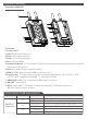


3. Appearance Instruction
Transmitter CURVE500
⑴ Antenna
⑵ Product label
⑶ Link:Wireless status indicator
⑷ Video:Video signal indicator
⑸ Power:Power status indicator
⑹ Pair:0.96-inch OLED
⑺ Installation thread:1/4”-20 thread. Use the package supplied articulating arm trestle to install
the device to the camera.
⑻ USB:Micro USB,software upgrade interface
⑼ HDMI in:HDMI input (standard HDMI-A type connector).
⑽ Battery plate:“F” plates can be used. We recommend SWIT batteries like: S-8972, S-8970,
S-8770, S-8975 compatible with SONY “ L” series NP-F770/970.
⑾ HDMI LOOP:HDMI loop out (standard HDMI-A type connector).
⑿ ON/ OFF:Power switch
⒀ DC in:Support DC 7~17V input,5.5mm(outer diameter)/2.1mm(inner diameter)
Outside: negative, Inside: positive
Status
Constant On
Off
Constant On
Flash
Constant On
Flash
Description
Power connected and switched on
Power disconnected and switched off
There is recognizable video signal input
There is no recognizable video signal input
The wireless network connection is normal
The wireless network connection is abnormal
Device
CURVE500
Transmitter
LED indicator
Power
Video
Link
The description of LED status indicator
(1)
(2)
(3)
(4)
(5)
(6)
(7)
(8)
(9)
(10)
(11)
(12)
(13)