OPERATING GUIDE IP ADVANCED RADIO SYSTEM IP501M INTRODUCTION 1 1.BEFORE BEFOREUSING USING 2 2.BASIC BASICOPERATION OPERATION 3 3.ADVANCED ADVANCEDOPERATION OPERATION 4 4.SET SETMODE MODE 5 5.OPTIONS OPTIONS 6 6.
INTRODUCTION Thank you for choosing this Icom product. This product is designed and built with Icom’s state of the art technology and craftsmanship. With proper care, this product should provide you with years of trouble-free operation. Features ••Communication throughout the Coverage of LTE (4G) and 3G Network ••Built-in Bluetooth® and GPS* An external GPS antenna is supplied.
BEFORE USING Section 1 Supplied accessories…………………………………………………………………………………………………… 1-2 Rear panel connection………………………………………………………………………………………………… 1-3 Mounting the transceiver………………………………………………………………………………………………… 1-5 Panel Description………………………………………………………………………………………………………… 1-6 MMFront Panel………………………………………………………………………………………………………… 1-6 DDIAL..........................................................................................................................................................
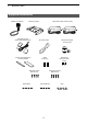
1 BeFORe uSIng Supplied accessories Speaker microphone Mounting bracket gPS antenna and double-sided adhesive pad LTe antennas (with cleaning cloth) Cushion and sheet for the mounting bracket Terminals for DC power cable (R2-6) Spare fuses (5A) Self-tapping screws (M5×20 mm) Mounting screws (M5×12 mm) Flat washers Microphone hanger and screw set DC power cable Spring washers 1-2 nuts
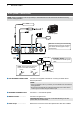
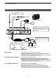
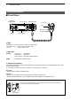
1 BeFORe uSIng Rear panel connection NOTE: Keep at a distance of 20 cm (8 inches) or more between the LTe antenna of this device and any persons during operation. Optional speaker 1 23 4 5 6 TIP: After connecting the LTe Antennas and gPS Antenna, wrap the connectors with rubber vulcanizing tape to help in waterproofing. 1 7 Red Black Fuse holders R WARNING! NEVER remove the fuse holders from the DC power cable. NOTE: use the terminals as shown below for the cable connections.
1 BeFORe uSIng Rear panel connection Optional speaker 1 23 4 5 6 1 TIP: After connecting the LTe Antennas and gPS Antenna, wrap the connectors with rubber vulcanizing tape to help in waterproofing. 7 Red Black Fuse holders R WARNING! NEVER remove the fuse holders from the DC power cable. NOTE: use the terminals as shown below for the cable connections. Crimp Solder 12 V or 24 V Battery 5 LAN CABLE ………………… Connect the network devices such as a switch.
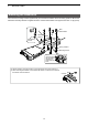
1 Before using Mounting the transceiver he universal mounting bracket supplied with your transceiver enables various mounting positions. Mount the T transceiver securely with the 4 supplied screws to a thick surface which can support more than 1.5 kg (3.3 lb). Nuts Flat washers Mounting bracket Self-tapping screws Spring washers Mounting screws When removing, slide the transceiver towards you while push the lever. To reduce vibration, place the cushion on the transceiver and put the sheet on it.
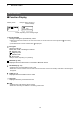
1 BeFORe uSIng Panel Description ■ Front Panel Indicators [TX/RX] [MSg] Function display Microphone jack IP501M Option key [PTT] Microphone Speaker [DIAL] Operating keys D DIAL Hold down for 1 second to turn the transceiver On or OFF. • On standby screen: • Others: Rotate to adjust the audio volume. Rotate to select an item. D Indicators [TX/RX] Lights red: Transmitting Lights green: Receiving Lights orange: Receiving and transmitting [MSG] Reserved for a future function.
1 Before using Panel Description DDOperating keys Assigned key functions may differ, depending on the presetting. [Address] key ••Selects a preset address. ••Push to toggle the Address Book between the call types. LLYou can also toggle the address by rotate [DIAL]. All → Group (Talkgroup) → Individual [Call History] key ••Push to display the call history. ••Push this key several times to toggle between the Call his types, Transmitted call, Received call, Sent message, and Received message.
1 Before using Panel Description ■■Function Display Standby screen Example: When receiving a custom message 10/14 12:00 All 10/14 13:00 Everyone meet NOW Scrolls, depending on the message length :S ignal strength The signal strength is represented by 3 bars. LLWhen the transceiver location is out of the service area, or cannot receive the control signal, the icon blinks. LLIf the IP501M has not been authenticated, is displayed. (out-of-area) : Call types Shows the call type.
BASIC OPERATION Section 2 Basic operation…………………………………………………………………………………………………………… 2-2 MMTurning the transceiver ON or OFF……………………………………………………………………………… 2-2 MMReceiving and Transmitting……………………………………………………………………………………… 2-2 Using the Address book………………………………………………………………………………………………… 2-3 DSelecting D a call-to party from the Address book........................................................................................2-3 DSelecting D a call-to party from the Call history..............................
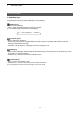
2 BASiC OpeRATiON Basic operation ■ Turning the transceiver ON or OFF Turning ON: Hold down [DiAL] for 1 second to turn ON the transceiver. • The standby screen is displayed as shown to the right. L It may take a few minutes to boot up the transceiver for the first time. Turning OFF: Hold down [DiAL] for 1 second to turn OFF the transceiver. ip501M Ver. x.x.xx/x Connecting... 00002 Setting up...
2 Basic operation Using the Address book You can select a call-to party from the Address book or Call history. DDSelecting a call-to party from the Address book The [Address] key can be used, depending on a preset. Ask your dealer for details. About the call type: All call: Transmit to all of the transceivers that belongs to the network. Group call: Transmit to the transceivers that belongs to the same group. Talkgroup call: See page 3-4 for details.
ADVANCED OPERATION Section 3 Sending a message (Message Call)…………………………………………………………………………………… 3-2 MMSelecting a call-to party…………………………………………………………………………………………… 3-2 MMSending a message……………………………………………………………………………………………… 3-2 DSending D a preset message........................................................................................................................3-2 DCreating D and sending a message using the optional HM-230HB.............................................................
3 advanced operation Sending a message (Message Call) You can send a message, depending on a presetting. Ask your dealer for details. ■■Selecting a call-to party 1. Push [Address] to display the Address book. ••The Address book is displayed. 2. Push [Address] several times to toggle the call type. LLDisplayed call type may differ, depending on the presetting. All → Group → Individual → Telephone Individual 00002 Sales2 3. Rotate [DIAL] to select a call-to party.
3 advanced operation Browsing received messages You can browse received messages, depending on the presetting. Ask your dealer for details. 1. Push [Call History] to display the Call history. ••The Call history is displayed. 2. Push [Call History] to display “Rx MSG log.” LLMay be required to push [Call History] several times, depending on the presetting. 3. Rotate [DIAL] to browse received messages. LLThe selected message may scroll, depending on the message length.
3 advanced operation About the Talkgroup Call The Talkgroup Call function enables the user to communicate with call-to parties in the same Talkgroup. For example, in the illustration below, when IP501M “00004” in its normal group “10001” selects Talkgroup “20001,” it is excluded from group “10001,” and can communicate with only IP501Ms “00006” and “00008” that belong to the Talkgroup “20001.
3 advanced operation About the Talkgroup Call DDSelecting a Talkgroup number You can select a Talkgroup number if the Talkgroup Call function is assigned to the [FUNC] or [Address] key. Ask your dealer for details. Selecting with a [FUNC] key: 1. Push [FUNC] to display the Function. ••The Function is displayed. 2. Push [FUNC] to display “Talkgroup,” if the other function is displayed. LLMay be required to push [FUNC] several times, depending on the presetting. 3.
3 advanced operation Emergency Call function You can receive or transmit Emergency Call if the function is assigned to the Option key or [Call History] key. Ask your dealer for details. Transmitting: LLThe instruction is based on the case that the function is assigned to the Option key. 1. Hold down the Option key until “Emergency” is displayed. ••An alarm sounds periodically. LLIf the Silent mode is enabled by your dealer, no alarm sounds, and no emergency indication is displayed. Emergency Sales2 2.
3 advanced operation Other functions DDPocket Beep function The Pocket beep function sounds a notification tone and indication when a call is received. LLThis function is set by your dealer, or in the Set mode. LL“ ” is displayed when the function is ON. LL“ ” blinks and the notification beep sounds when a call is received. It blinks until the transceiver return to the standby mode after a received signal disappears.
SET MODE Section 4 Using the Set mode……………………………………………………………………………………………………… 4-2 DBasic D Set mode.........................................................................................................................................4-2 DDetailed D Set mode.....................................................................................................................................4-2 DUsing D the Set mode............................................................................................
4 set mode Using the Set mode You can use the Set mode to set infrequently changed values or function settings. The transceiver has 2 types of Set mode, as shown below. LLYou cannot transmit or receive while the transceiver is in the Set mode. DDBasic Set mode zz Hold down [FUNC] for 3 seconds to enter the Set mode. ••“SET” is displayed. SET LOG ––– DDDetailed Set mode 1. Hold down [FUNC] for 3 seconds to enter the Set mode. ••“SET” is displayed. 2.
4 set mode Set mode items The shaded items are also displayed in the Basic Set mode. LLItems or default values may be different, depending on the transceiverʼs version or presettings. Ask your dealer for details. Item LOG Description Option/range Deletes logs. Default – – –, CLR ––– NO or YES NO NO or YES NO Enable or Disable Enable Enable or Disable Enable Disable, Tone1 ~ Tone8 Tone1 (Pi) LLSelect “CLR,” and then push [Call History] to delete.
4 set mode Set mode items The shaded items are also displayed in the Basic Set mode. LLItems or default values may be different, depending on the transceiverʼs version or presettings. Ask your dealer for details. Item VOX Threshold Description Option/range Sets the VOX threshold level. Default 0% ~ 100% 40% Enable or Disable Enable Enable or Disable Enable LLLower values make the VOX function more sensitive to your voice.
4 set mode Set mode items The shaded items are also displayed in the Basic Set mode. LLItems or default values may be different, depending on the transceiverʼs version or presettings. Ask your dealer for details. Item Description Option/range Default BT Auto Connect* Selects whether or not to automatically connect a Enable or Disable Bluetooth device. Enable Selects whether or not to synchronize the Bluetooth Disable or Enable headsetʼs volume level with the transceiverʼs volume level.
4 set mode Set mode items The shaded items are also displayed in the Basic Set mode. LLItems or default values may be different, depending on the transceiverʼs version or presettings. Ask your dealer for details. Item BT One Touch PTT*1 Description Option/range Selects whether or not to enable the One-Touch PTT Disable or Enable function while a Bluetooth headset is connected. The function toggles receiving and transmitting by momentarily pushing [PTT] on a Bluetooth headset.
4 set mode Set mode items The shaded items are also displayed in the Basic Set mode. LLItems or default values may be different, depending on the transceiverʼs version or presettings. Ask your dealer for details. Item Description Option/range Default Show Network Select Selects whether or not to display the “Network Selectˮ item by pushing [FUNC] on the standby screen. Disable or Enable Disable Network Select Selects whether or not to automatically select a network carrier.
OPTIONS Section 5 Options…………………………………………………………………………………………………………………… 5-2 Using the HM-230HB command microphone………………………………………………………………………… 5-3 MMConnecting the HM-230HB……………………………………………………………………………………… 5-3 MMPanel description…………………………………………………………………………………………………… 5-3 Using the Bluetooth® device…………………………………………………………………………………………… MMAbout the VS-3 Bluetooth headset……………………………………………………………………………… MMPairing with a Bluetooth device…………………………………………………………………………………… MMSettings for the Bluetooth function………………………
5 OPTIONS Options LLSome options may not be available in all countries. Ask your dealer for details. Microphones External speakers ••HM-230HB command microphone ••HM-241 speaker microphone Same as supplied ••SM-28 desktop microphone (Input impedence: 4 Ω) ••SP-30 external speaker Rated input 20 W, Maximum input 30 W, Cable length: Approximately 2.8 m (9.2 feet) ••SP-35 external speaker Rated input 5 W, Maximum input 7 W, Cable length: Approximately 2 m (6.
5 OPTIONS Using the optional HM-230HB command microphone You can use the transceiver more comfortable using the HM-230HB command microphone. ■■Connecting the HM-230HB Turn OFF the transceiver, and insert the HM-230HB connector into the microphone jack until it locks.
5 OPTIONS Using the optional HM-230HB command microphone ■■Using Option keys The function shown below may be usable by using Option keys, depending on the presetting. Ask your dealer for details. Option key [Emergency] Function Message Description Push an Option key to display the “Message.” You can select a preset message to send. Edit Message Push an Option key to display the “Create Message.” You can create and send a message (p. 3-2).
5 OPTIONS Using a Bluetooth® device You can connect to a Bluetooth device with built-in Bluetooth wireless technology. LLOnly the VS-3 headset performance is guaranteed as of August 2019. ••The Bluetooth function may not be usable, depending on the presetting. Ask your dealer for details. ••The communication range of Bluetooth is approximately 10 m (33 ft). LLMay vary, depending on the environment in which the device operates.
5 OPTIONS Using the Bluetooth® device ■■Pairing with a Bluetooth device This is an example of connecting the transceiver to a VS-3 Bluetooth headset. 1. Turning ON the transceiver’s Bluetooth function 1. Hold down [FUNC] for 3 seconds to enter the Set mode. 2. Push [FUNC] or [Address] several times to select “Bluetooth.” 3. Rotate [DIAL] to select “Enable,” and then push [Call History] to turn ON the Bluetooth function. SET Bluetooth Enable 2. Entering the VS-3 Pairing mode 1.
5 OPTIONS Using the Bluetooth® device ■■Disconnecting a paired device You can disconnect a paired Bluetooth device if it is not being used. 1. In the standby screen, push [FUNC] several times to select “Pairing List.” 2. Select the device to disconnect, and then push [Call History]. ••“Unconnected” is displayed if the headset or device is correctly disconnected. LLDo the same steps to reconnect to the Bluetooth device.
5 OPTIONS Using the Bluetooth® device ■■Initializing the Pairing lists If you have problems with Bluetooth operation, initialize the pairing lists, as shown below. Initializing the Pairing list of the transceiver LLAll the paired Bluetooth devices are deleted from the Pairing list by the initialization. LLThe Pairing list is not initialized by the RESET function in the Detailed Set mode. 1. 2. 3. 4. In the Standby screen, hold down [FUNC] for 3 seconds to enter the Set mode.
FOR YOUR REFERENCE Section 6 Troubleshooting………………………………………………………………………………………………………… 6-2 Specifications…………………………………………………………………………………………………………… DD General…………………………………………………………………………………………………………… DD LAN……………………………………………………………………………………………………………… DD Audio……………………………………………………………………………………………………………… DD 3G (W-CDMA)…………………………………………………………………………………………………… DD LTE……………………………………………………………………………………………………………… DD GNSS…………………………………………………………………………………………………………… DD Bluetooth………………………………………………………………………………………………………… 6-1 6-
6 FOR YOUR REFERENCE Troubleshooting The following conditions are not due to a malfunction. Check before sending a request for repair. No power comes ON. ••Bad connection to the power supply. - Check the connection to the transceiver and power supply. (p. 1-3) ••Fuse is blown. - Find the cause, repair, and then replace the fuse. The “ ” blinks, or “Connecting...” is displayed (standby screen is not displayed) ••The transceiver is located out of the service area. - Move your location.
6 FOR YOUR REFERENCE Specifications LLMeasurements made without an antenna. LLAll stated specifications are subject to change without notice or obligation. DDGeneral Power supply Current drain Operating Temperature environment Humidity Dimensions (Projections not included) Weight Regulatory USA version Compliance European version Interface Australian version IP code DC 13.8 V ±10%/DC 26.4 V ±10% 1.2 A maximum (DC 13.8 V), 0.8 A maximum (DC 26.
6 FOR YOUR REFERENCE Specifications DDGNSS GPS GLONASS 1575.42 MHz ±1.023 MHz 1597.5 ~ 1605.8 MHz DDBluetooth Frequency range Transmission power Version Profile 2402 ~ 2480 MHz Conduct 4.5 dBm Bluetooth Version 2.
A7536-2EX-0a © 2019 Icom Inc. Aug.