MC3000 User Guide
MC3000 User Guide 72-68899-02 Rev 1 August 2005
© 2005 by Symbol Technologies, Inc. All rights reserved. No part of this publication may be reproduced or used in any form, or by any electrical or mechanical means, without permission in writing from Symbol. This includes electronic or mechanical means, such as photocopying, recording, or information storage and retrieval systems. The material in this manual is subject to change without notice. The software is provided strictly on an “as is” basis.
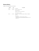
Revision History Changes to the original manual are listed below: Change Date Description -01 Rev A Dec. 2004 Initial Release -01 Rev B June 2005 Added Four Slot Ethernet cradle. Added Fabric Holster. Appendix A, added Accessory Specifications. Added Appendix C, Regulatory. -02 Rev A Sept. 2005 Pages 2-13 and 2-29, removed WZC, replaced with wireless application description. Global changes: Changed Windows CE.NET 4.2 to Windows CE.NET 5.
Contents Revision History . . . . . . . . . . . . . . . . . . . . . . . . . . . . . . . . . . . . . . . . . . . . . . . . . . . . . . . . . . . . . . . . . . . . . . . . . . . iii About This Guide Introduction . . . . . . . . . . . . . . . . . . . . . . . . . . . . . . . . . . . . . . . . . . . . . . . . . . . . . . . . . . . . . . . . . . . . . . . . . . . . . xiii Documentation Set . . . . . . . . . . . . . . . . . . . . . . . . . . . . . . . . . . . . . . . . . . . . . . . . . . . . . . . . . . . . . .
vi MC3000 User Guide Starting the Mobile Computer . . . . . . . . . . . . . . . . . . . . . . . . . . . . . . . . . . . . . . . . . . . . . . . . . . . . . . . . . . . . . .1-12 Calibration Screen . . . . . . . . . . . . . . . . . . . . . . . . . . . . . . . . . . . . . . . . . . . . . . . . . . . . . . . . . . . . . . . . . . .1-12 Demo Window . . . . . . . . . . . . . . . . . . . . . . . . . . . . . . . . . . . . . . . . . . . . . . . . . . . . . . . . . . . . . . . . . . . . . .
Contents vii File System Directory Structure . . . . . . . . . . . . . . . . . . . . . . . . . . . . . . . . . . . . . . . . . . . . . . . . . . . . . . . . . . . . .2-26 Connecting to the Internet on a Wireless LAN Network . . . . . . . . . . . . . . . . . . . . . . . . . . . . . . . . . . . . . . . . . .2-27 Chapter 3. Using Bluetooth Introduction. . . . . . . . . . . . . . . . . . . . . . . . . . . . . . . . . . . . . . . . . . . . . . . . . . . . . . . . . . . . . . . . . . . . . . . . . . . . .
viii MC3000 User Guide Security Tab . . . . . . . . . . . . . . . . . . . . . . . . . . . . . . . . . . . . . . . . . . . . . . . . . . . . . . . . . . . . . . . . . . . . . . . .3-28 Discovery Tab . . . . . . . . . . . . . . . . . . . . . . . . . . . . . . . . . . . . . . . . . . . . . . . . . . . . . . . . . . . . . . . . . . . . . . .3-29 Virtual COM Port Tab . . . . . . . . . . . . . . . . . . . . . . . . . . . . . . . . . . . . . . . . . . . . . . . . . . . . . . . . . . . . . . . . .
Contents ix Cables . . . . . . . . . . . . . . . . . . . . . . . . . . . . . . . . . . . . . . . . . . . . . . . . . . . . . . . . . . . . . . . . . . . . . . . . . . . . . .5-9 Appendix A. Technical Specifications Mobile Computer And Accessory Technical Specifications . . . . . . . . . . . . . . . . . . . . . . . . . . . . . . . . . . . . . . . A-3 Appendix B. Keypad Functions/Special Characters Introduction. . . . . . . . . . . . . . . . . . . . . . . . . . . . . . . . . . . . . . . . . . . . . . . . .
x MC3000 User Guide
About This Guide Contents Introduction . . . . . . . . . . . . . . . . . . . . . . . . . . . . . . . . . . . . . . . . . . . . . . . . . . . . . . . . . . . . . . . . . . . . . . . . . . . . . . xi Documentation Set . . . . . . . . . . . . . . . . . . . . . . . . . . . . . . . . . . . . . . . . . . . . . . . . . . . . . . . . . . . . . . . . . . . . . . . . . . . . . . xi Configurations . . . . . . . . . . . . . . . . . . . . . . . . . . . . . . . . . . . . . . . . . . . . . . . . . . . . . . . . . . . . .
xii MC3000 User Guide
xiii Introduction This guide provides information about using the MC3000 mobile computers and accessories. Screens and windows pictured in this guide are samples and may differ from actual screens. Documentation Set The documentation set for the MC3000 is divided into guides that provide information for specific user needs. • • • • • Microsoft Application Guide - describes how to use Microsoft developed applications. Symbol Application Guide - describes how to use Symbol developed applications.
xiv MC3000 User Guide Configurations This guide covers the following configurations: MC3000-K - optional Bluetooth radio, color or monochrome display, 64MB/64MB memory, imager, Windows CE .NET 5.0 Core or Windows CE .NET 5.0 Professional Operating System. MC3000-R - optional Bluetooth radio, color or monochrome display, 32MB/64MB or 64MB/64MB memory, laser scanner in rotating turret, Windows CE .NET 5.0 Core or Windows CE .NET 5.0 Professional Operating System. MC3090-G - 802.
xv Notational Conventions The following conventions are used in this document: • • • • • The term “mobile computer” refers to the Symbol MC3000. Italics are used to highlight the following: • Chapters and sections in this and related documents • Dialog box, window and screen names • Drop-down list and list box names • Check box and radio button names • Icons on a screen. Bold text is used to highlight the following: • Key names on a keypad • Button names on a screen.
xvi MC3000 User Guide Service Information If an equipment problem occurs, contact the appropriate regional Symbol Support Center, see page xvi for contact information. Before calling, have the model number, serial number and several bar code symbols at hand. Call the Support Center from a phone near the scanning equipment so that the service person can try to talk through the problem.
xvii Finland/Suomi Oy Symbol Technologies Kaupintie 8 A 6 FIN-00440 Helsinki, Finland 9 5407 580 (Inside Finland) +358 9 5407 580 (Outside Finland) France Symbol Technologies France Centre d'Affaire d'Antony 3 Rue de la Renaissance 92184 Antony Cedex, France 01-40-96-52-21 (Inside France) +33-1-40-96-52-50 (Outside France) Germany/Deutschland Symbol Technologies GmbH Waldstrasse 66 D-63128 Dietzenbach, Germany 6074-49020 (Inside Germany) +49-6074-49020 (Outside Germany) Italy/Italia Symbol Technologies
xviii MC3000 User Guide Sweden/Sverige “Letter” address: Symbol Technologies AB Box 1354 S-171 26 SOLNA Sweden Visit/shipping address: Symbol Technologies AB Solna Strandväg 78 S-171 54 SOLNA Sweden Switchboard: 08 445 29 00 (domestic) Call Center: +46 8 445 29 29 (international) Support E-Mail: Sweden.Support@se.symbol.com If the Symbol product was purchased from a Symbol Business Partner, contact that Business Partner for service.
Getting Started Chapter Contents Introduction . . . . . . . . . . . . . . . . . . . . . . . . . . . . . . . . . . . . . . . . . . . . . . . . . . . . . . . . . . . . . . . . . . . . . . . . . . . . . 1-3 Unpacking the Mobile Computer . . . . . . . . . . . . . . . . . . . . . . . . . . . . . . . . . . . . . . . . . . . . . . . . . . . . . . . . . . . . . 1-3 Accessories . . . . . . . . . . . . . . . . . . . . . . . . . . . . . . . . . . . . . . . . . . . . . . . . . . . . . . . . . . . . . . . . . . . . . .
1-2 MC3000 Integrator Guide
Getting Started 1-3 Introduction This chapter describes the mobile computer physical characteristics, how to install and charge the batteries, how to remove and replace the Strap/Door Assembly and how to start the mobile computer for the first time. Unpacking the Mobile Computer Carefully remove all protective material from around the mobile computer and save the shipping container for later storage and shipping.
1-4 MC3000 Integrator Guide Accessories Table 1-1 lists the MC3000 accessories. Table 1-1. MC3000 Accessories Accessory Description Single Slot Serial/USB Cradle Charges the mobile computer main battery and a spare battery, and synchronizes the mobile computer with a host computer through either a serial or USB connection. Four Slot Charge Only Cradle Charges up to four mobile computers. Four Slot Ethernet Cradle Charges up to four mobile computers and provides Ethernet communications.
Getting Started 1-5 Parts There are three versions of the MC3000 mobile computers, the MC3000 1D/2D Imager (MC3000-K or MC3090-K) , the MC3000 Laser with Rotating Scan Turret (MC3000-R or MC3090-R) and the MC3090 Gun (MC3090-G). For more information on the Rotating Scan Turret, see Figure 1-3 on page 1-6.
1-6 MC3000 Integrator Guide Headset Jack (optional) Scan Window Scan Window Strap/Door Assembly Screws Headset Jack (optional) Stylus Strap/Door Assembly Stylus Holder Latches MC3000-K MC3000-R Figure 1-2. MC3000 Imager and MC3000 Laser Mobile Computers (Back View) Rotating Scan Turret The MC3000-R mobile computer features a Rotating Scan Turret with three position stops. This feature offers greater scanning flexiblilty. Position Stop Position Stop Position Stop Figure 1-3.
Getting Started 1-7 Microphone (optional) Scan LED Indicators (red/green) Charge LED Indicator (amber) Indicator LED Bar Display Scan Button Keypad Power Scan LED Indicator (red/green) Trigger Figure 1-4. MC3000-G Mobile Computer Mobile Computer Startup To start using the mobile computer: • • • Install the main battery. Charge the main battery and the backup battery. Start the mobile computer. Install Main Battery If the main battery is charged, the mobile computer can be used immediately.
1-8 MC3000 Integrator Guide 3. Insert the battery into the slot, bottom first and press the battery gently into the slot. The battery clip locks the battery into place. 4. With the latches in the open position, replace the Strap/Door Assembly, top first and press to close. 5. Rotate the latches (to the lock position) to lock the Strap/Door Assembly in place. Latches Hand Strap Battery Clip Battery Slot Battery Strap/Door Assembly Figure 1-5.
Getting Started 1-9 Latches Hand Strap Battery Strap/Door Assembly Battery Removal Tab Strap/Door Assembly Figure 1-6.
1-10 MC3000 Integrator Guide Battery Charging Use the mobile computer cradles, cables and spare battery chargers to charge the mobile computer main battery. The main battery can be charged before insertion into the mobile computer or after it is installed. There are two main batteries for the MC3000, the Standard Battery and the Extended Life Battery. Either battery can be used, but the Extended Life Battery requires a different Strap/Door Assembly.
Getting Started 1-11 Table 1-2. Mobile Computer LED Charge Indicators LED Off Indication Mobile computer not placed correctly in the cradle; charge cable not connected correctly; charger is not powered. Fast Blinking Amber Error in charging; check placement of the mobile computer. Slow Blinking Amber Mobile computer is charging. Solid Amber Charging complete.
1-12 MC3000 Integrator Guide Starting the Mobile Computer When the mobile computer is powered on for the first time, it initializes. The Symbol Splash screen appears for a short period of time, followed by the Calibration screen. Figure 1-7. Symbol Splash Screen After the calibration procedure is performed the factory settings launch the Demo window. Application specific shells may provide application specific windows instead of the Demo window. These screens also appear when a cold boot is performed.
Getting Started 1-13 Demo Window The Demo window is the factory default menu. On initial power up (or on a warm or cold boot) the Demo window appears. These sample/demo applications are intended to be used by application developers as application development examples. These applications were not developed to support end users. Refer to the Symbol Application Guide for information about the Demo window applications. Figure 1-9.
1-14 MC3000 Integrator Guide b. On the MC3000-G, pull the battery release tab to unclip the battery and lift the battery out top first. Strap/Door Assembly Latches Hand Strap Battery Battery Clip Figure 1-10. Main Battery Removal (MC3000-K/R) Latches Strap/Door Assembly Battery Clip Battery Hand Strap Figure 1-11. Main Battery Removal (MC3000-G) The SD card holder is located under the battery.
Getting Started 1-15 Strap/Door Assembly Removal and Replacement (MC3000-K/R) The Strap/Door Assembly consists of a hand strap and the battery door. There are two versions of this assembly, one for the Standard Battery and one for the Extended Life Battery. Before removing the Strap/Door Assembly, press the red Power button to turn off the screen and set the mobile computer to suspend mode. To remove the Strap/Door Assembly: 1. Rotate the latches to the open position.
1-16 MC3000 Integrator Guide Strap/Door Assembly Removal and Replacement (MC3000-G) The Strap/Door Assembly consists of a hand strap and the battery door. Before removing the Strap/Door Assembly, press the red Power button to turn off the screen and set the mobile computer to suspend mode. To remove the Strap/Door Assembly: 1. Rotate the latches to the open position. Do not lift up on the latches when removing the Strap/Door Assembly. Lift up on the Hand Strap only. 2.
Operating the MC3000 Chapter Contents Introduction . . . . . . . . . . . . . . . . . . . . . . . . . . . . . . . . . . . . . . . . . . . . . . . . . . . . . . . . . . . . . . . . . . . . . . . . . . . . . 2-3 Power Button . . . . . . . . . . . . . . . . . . . . . . . . . . . . . . . . . . . . . . . . . . . . . . . . . . . . . . . . . . . . . . . . . . . . . . . . . . . . 2-3 Keypads . . . . . . . . . . . . . . . . . . . . . . . . . . . . . . . . . . . . . . . . . . . . . . . . . . . . . . . . . . . . . . .
2-2 MC3000 User Guide Data Capture. . . . . . . . . . . . . . . . . . . . . . . . . . . . . . . . . . . . . . . . . . . . . . . . . . . . . . . . . . . . . . . . . . . . . . . . . . . .2-19 Laser Scanning . . . . . . . . . . . . . . . . . . . . . . . . . . . . . . . . . . . . . . . . . . . . . . . . . . . . . . . . . . . . . . . . . . . . . .2-19 Scan LED Indicators . . . . . . . . . . . . . . . . . . . . . . . . . . . . . . . . . . . . . . . . . . . . . . . . . . . . . . . . . . . . . . . . . .
Operating the MC3000 2-3 Introduction This chapter provides basic instructions for using the mobile computer and navigating the mobile computer software. Power Button Press the red Power button to toggle the mobile computer between suspend and resume. When the screen is off the mobile computer is in suspend mode and when the screen is on the mobile computer is on. Keypads The mobile computer is available with the following keypad configurations: • • • 28-key keypad 38-key keypad 48-key keypad.
2-4 MC3000 User Guide 28-Key Keypad The 28-key keypad contains a Power button, application keys, scroll keys and function keys. The keypad is color-coded to indicate the alternate function key (blue) values and the alternate ALPHA key (orange) values. Note that keypad functions can be changed by an application so the mobile computer keypad may not function as described. See Table 2-2 on page 2-4 for key and button descriptions and Table 2-1 on page 2-3 for the keypad special functions. Figure 2-1.
Operating the MC3000 2-5 Table 2-2. 28-Key Descriptions (Continued) Key Description Scroll Up and Down Moves up and down from one item to another. Increases/decreases specified values. Scroll Left and Right Moves left and right from one item to another. Increases/decreases specified values. Produces a TAB when the blue FUNC key is activated and the right arrow key is pressed. ESC Produces the ESC function by default.
2-6 MC3000 User Guide Table 2-2. 28-Key Descriptions (Continued) Key Display backlight Description Toggles the display backlight on and off.
Operating the MC3000 2-7 38-Key Keypad The 38-key keypad contains a Power button, application keys, scroll keys and function keys. The keypad is color-coded to indicate the alternate function key (blue) values. Note that keypad functions can be changed by an application so the mobile computer keypad may not function as described. See Table 2-3 on page 2-7 for key and button descriptions and Table 2-1 on page 2-3 for the keypad special functions. Figure 2-2. 38-Key Keypad Table 2-3.
2-8 MC3000 User Guide Table 2-3. 38-Key Descriptions (Continued) Key Description Scan (yellow) Used in scanning applications, press to scan a bar code. Scroll Left and Right Moves left and right from one item to another by default. Produces a TAB when the blue FUNC key is activated and the right arrow key is pressed. Scroll Up and Down Moves up and down from one item to another by default.
Operating the MC3000 2-9 Table 2-3. 38-Key Descriptions (Continued) Key Display backlight Description Toggles the display backlight on and off.
2-10 MC3000 User Guide 48-Key Keypad The 48-key keypad contains a Power button, application keys, scroll keys and function keys. The keypad is color-coded to indicate the alternate function key (blue) values. Note, that keypad functions can be changed by an application so the mobile computer keypad may not function as described. See Table 2-3 on page 2-7 for key and button descriptions and Table 2-1 on page 2-3 for the keypad special functions. Figure 2-3. 48-Key Keypad Table 2-4.
Operating the MC3000 2-11 Table 2-4. 48-Key Descriptions (Continued) Key Description Numeric/Scroll/Select ... Numeric, scroll, select keys. Numeric by default. With the orange key activated, the 2, 4, 6, and 8 keys produce scroll functions and the 5 key produces a select function. With the FUNC key activated, 7 produces the ESC function and 9 produces the TAB function. Shift Press and release the SHIFT key to activate the keypad alternate SHIFT functions.
2-12 MC3000 User Guide Demo Window On initial power up (or on a warm or cold boot) the Demo window appears. This window links to the Test Applications window and the two windows provide the sample/demo applications. The sample/demo applications are intended to be used by application developers as application development examples. These applications were not developed to support end users. Refer to the Symbol Application Guide for the Demo window applications.
Operating the MC3000 2-13 Taskbar The taskbar (at the bottom of the screen) displays the Start button, active programs, battery status and communication status. The taskbar icons are described in Table 2-5. The taskbar icons display the function status, indicate what programs are active and indicate the battery charge status. The Taskbar buttons are used to access menus, select/deselect functions or to change display windows. • • • Status Icons: The status icons indicate the function key status.
2-14 MC3000 User Guide Table 2-5. Taskbar Icons (Continued) Icon Description Indicates that the SHIFT button function is selected. Indicates that the FUNC button function is selected. Indicates that the CTRL button function is selected. ALT Indicates that the ALT character selection is selected. Indicates that the mobile computer is in ALPHA button mode is selected. Battery Unknown Icon The Battery Unknown icon displays when communication with the smart battery has not been established.
Operating the MC3000 2-15 Programs Menu From the Start menu, tap Programs to launch the Programs menu. The programs provided with Windows CE .NET 5.0 Professional and Windows CE .NET 5.0 Core are displayed in the Programs menu. Refer to the Symbol Application Guide, p/n 72-68901-xx and the Microsoft® Applications User Guide for Symbol Devices, p/n 72E-68197-xx for application information. Windows CE .NET 5.0 Professional Windows CE .NET 5.0 Core Figure 2-8.
2-16 MC3000 User Guide Task Manager 1. Select FUNC - CTRL, (to activate the ALT state) and tap on the taskbar to display the Task Manager, Properties Selection menu. Figure 2-9. Task Manager, Properties Selection Menu 2. Tap Task Manager to display the Task Manager window. Figure 2-10. Task Manager Window 3. Tap a task in the Active Tasks list and tap Switch To to make that task the primary task, or tap End Task to end the selected task. 4. Tap X to exit the Task Manager window. Properties 1.
Operating the MC3000 2-17 Advanced Tab 1. Tap the Advanced tab to enter the Taskbar and Start Menu, Advanced tab. 2. Tap the Clear button to delete all of the documents listed in the Start - Documents entry, see Start Button on page 2-14. Typically this list is empty, but if there were documents in the list the Clear button would delete them. 3. Tap the Expand Control Panel checkbox to display the entire contents of the MS control panel in list form, rather than icons. Figure 2-12.
2-18 MC3000 User Guide Entering Data via the Bar Code Scanner The sample bar code scanner application scans data into data fields in the same way data is entered via the keypad. Data Capture The mobile computer has an integrated scanner or imager that collects data by scanning bar codes. Laser Scanning To scan bar codes with the mobile computer: 1. 2. 3. 4. Ensure that the mobile computer is loaded with a scanning application.
Operating the MC3000 2-19 Scanning within range brings quick and constant decodes; scanning too close or too far away prevents decodes. Move the scanner closer and further away to find the right working range for the bar codes being scanned. However, the situation is complicated by the availability of various integrated scanning modules. The best way to specify the appropriate working range per bar code density is through a chart called a decode zone for each scan module.
2-20 MC3000 User Guide Table 2-7. MC3000-G/R, Laser Decode Ranges Bar Code Density Ranges Near Far 5.0 mil 2.0 in 5.08 cm 4.9 in 12.45 cm 7.5 mil 1.6 in 4.06 cm 7.9 in 20.07 cm 10 mil 1.2 in 3.05 cm 10.8 in 67.95cm UPC A 1.3 in 3.30 cm 12.7 in 32.26 cm 20 mil 1.4 in 3.56 cm 17.9 in 45.47 cm 40 mil 2.4 in 6.10 cm 26.4 in 67.06 cm 55 mil 3.4 in 8.64 cm 30.6 in 77.
Operating the MC3000 2-21 Decode Mode Activate the scan button, the mobile computer attempts to locate and decode enabled bar codes within its field of view. The mobile computer remains in this mode as long as the scan button remains activated, or until the bar code is decoded. Image Capture The imager version of the mobile computer allows image capture. In this mode, the imager displays an image until the image is snapped. The snapped image can then be saved.
2-22 MC3000 User Guide 3. Hold the mobile computer between two and nine inches (depending on symbol density) from the symbol, centering the aiming pattern cross hairs on the symbol. 4. Press the scan button. The Scan LED Indicators illuminate red to indicate that the laser is on. The Scan LED Indicators illuminate green and a beep sounds to indicate a successful decode. Imager Decode Ranges The decode ranges provide the decode distances for barcodes of specified densities.
Operating the MC3000 2-23 Table 2-8. MC3000-G/K, Imager Decode Ranges Bar Code Density Ranges Near Far 5.0 mil 4.5 in 11.43 cm 6.5 in 16.51cm 7.5 mil 3.3 in 8.38 cm 10.7 in 27.18 cm UPC A 2.5 in 6.35 cm 14.2 in 36.07cm 20 mil 2.8 in 7.11 cm 18.9 in 48.01 cm PDF417 6.67 mil 5.3 in 13.46 cm 7.7 in 19.56 cm PDF417 10 mil 4.3 in 10.92 cm 11.1 in 28.19 cm PDF417 15 mil 3.8 in 9.65 cm 14.4 in 36.
2-24 MC3000 User Guide Resetting the Mobile Computer If the mobile computer stops responding to input, reset it. There are two reset functions, warm boot and cold boot. A warm boot restarts the mobile computer by closing all running programs. All data that is not saved is lost. A cold boot also restarts the mobile computer, but erases all stored records and entries from RAM. In addition it returns formats, preferences and other settings to the factory default settings. Perform a warm boot first.
Operating the MC3000 2-25 Waking the Mobile Computer The default wakeup conditions define what actions wakeup the mobile computer. These settings are configurable and the factory default settings shown in Table 2-9 are subject to change/update. Table 2-9. Default Wakeup Conditions Status Power Off Description When the mobile computer is set to the suspend mode by pressing Power, these actions wake the mobile computer. Conditions for Wakeup 1. Power button is pressed. 2. AC power added or removed. 3.
2-26 MC3000 User Guide All files copied to the RAM based folders are lost after a cold boot. Connecting to the Internet on a Wireless LAN Network The mobile computer can connect to the Internet across a wireless LAN network. The Wireless Applications utility starts automatically when the mobile computer is turned on and the wireless application icon appears in the taskbar to indicate the connection and the signal strength status.
Using Bluetooth Contents
3-2 MC909X Integrator Guide
Using Bluetooth 3-3 Introduction Bluetooth-equipped devices can communicate without wires, using frequency-hopping spread spectrum (FHSS) RF to transmit and receive data in the 2.4 GHz Industry Scientific and Medical (ISM) band (802.15.1). Bluetooth wireless technology is specifically designed for short-range (30 feet/10 meters) communications and low power consumption. Mobile computers with Bluetooth capabilities can exchange information (e.g.
3-4 MC909X Integrator Guide Disabling Bluetooth To disable Bluetooth, tap Bluetooth icon - Disable Bluetooth. The Bluetooth icon changes to indicate that Bluetooth is disabled. Figure 3-1. Disable Bluetooth Enabling Bluetooth To enable Bluetooth, tap Bluetooth icon - Enable Bluetooth. The Bluetooth icon changes to indicate that Bluetooth is enabled. Figure 3-2.
Using Bluetooth 3-5 When the mobile computer is placed in suspend mode, the Bluetooth radio mode powers off and the piconet (Bluetooth connection) is dropped. When the mobile computer resumes, it take approximately 10 seconds for the Bluetooth radio driver to re-initialize the radio. Resume When the mobile computer resumes, Bluetooth turns on if it was on prior to suspend. Modes The BTExplorer application has two mode for managing Bluetooth connections: Wizard Mode and Explorer Mode.
3-6 MC909X Integrator Guide 4. Tap Next. The BTExplorer searches for Bluetooth devices in the area and displays the devices in the Select Remote Device window. Figure 3-4. Select Remote Device Window 5. Select a device from the list and then tap Next. The Connection Favorite Options window appears. Figure 3-5. Connection Favorite Options Window 6. Select Save As Favorite check box to save this service in the Favorite view. 7.
Using Bluetooth 3-7 8. Tap Next. The Connection Summary window appears. Figure 3-6. Connection Summary Window 9. Tap Connect to connect to the service.
3-8 MC909X Integrator Guide Explorer Mode The BTExplorer window is streamlined and easy to navigate and provides greater control to users familiar with Bluetooth functionality. The menu bar provides quick access to the options and tools used to connect to devices. Figure 3-7. Explorer Mode Window You can also use the “tap and hold” technique to view available options. Scroll bars and view options are like those you’re familiar with on your Windows desktop.
Using Bluetooth 3-9 3. Tap the Bluetooth icon and select Show BTExplorer. The BTExplorer window appears. Figure 3-8. BTExplorer Window 4. Tap and hold Remote Devices and select Discover Devices from the pop-up menu. The mobile computer searches for Bluetooth devices in the area. Figure 3-9. Discover Devices 5. The discovered devices display in the Untrusted Devices folder. Figure 3-10.
3-10 MC909X Integrator Guide Bonding with Discovered Device(s) A bond is a relationship created between the mobile computer and another Bluetooth device in order to exchange information in a secure manner. Creating a bond involves entering the same PIN on the two devices to bond. Once a bond is created, and the Bluetooth radios are turned on, the devices recognize the bond and are able to exchange information without re-entering a PIN. To bond with a discovered Bluetooth device: 1.
Using Bluetooth 3-11 7. The devices are successfully paired. The device name moves to the Trusted Devices folder. Figure 3-13. Bonded (Paired) Discovered Device Renaming a Bonded Device If it is necessary to rename a bonded device, it can be done from the BTExplorer window. 1. Launch BTExplorer. 2. Tap and hold the device to rename and select Rename in the pop-up menu. Figure 3-14.
3-12 MC909X Integrator Guide 3. The Change Device Name window appears. Figure 3-15. Change Device Name Window 4. Enter a new name for the bonded device in the text box. Tap OK. Deleting a Bonded Device If it is no longer necessary to connect with a device, delete it from the Bluetooth Bonded Devices window. 1. Launch BTExplorer. 2. Tap and hold the device to delete and.select Delete in the pop-up menu. Figure 3-16. Delete a Bonded Device 3. A confirmation dialog appears. Tap Yes.
Using Bluetooth 3-13 2. When prompted to bond with the remote device the PIN Code Request window appears. Figure 3-17. PIN Code Request Window 3. In the PIN Code: text box, enter the same PIN that was entered on the device requesting the bond. The PIN must be between 1 and 16 characters. 4. In the Device Name: text box, edit the name of the device requesting the bond, if desired. 5. Tap OK. 6. The bond is created and the mobile computer can now exchange information with the other device.
3-14 MC909X Integrator Guide 3. The mobile computer communicates with the remote device and then lists the services under the device name. Figure 3-19. List of Discovered Services Some examples of available services are: • File Transfer Services • Dial-Up Networking Services • Headset or Hands-Free Services • OBEX Object Push Services • Serial Port Services These services are discussed in the following paragraphs.
Using Bluetooth 3-15 8. Select a folder. The contents of the folder appear in the sub-window. Figure 3-20. Remote Device Folders 9. Tap and hold on the file. A pop-up menu appears. 10. Select the action to perform: a. New - create a new file or folder. on the remote device b. Delete - delete the selected file on the remote device. c. Get File - copy the file from the remote device to the mobile computer. d. Put File - copies a file from the mobile computer to the remote device.
3-16 MC909X Integrator Guide 3. Tap Open. The file is transferred from the mobile computer to the remote device. Connect to Internet Using Access Point This section explains how to access a Bluetooth-enabled LAN access point (AP) for a network connection. With this method of communication the Internet Explorer can be used to connect to a server. 1. 2. 3. 4. 5. 6. 7. 8. 9. 10. Ensure the mobile computer is discoverable and connectable. See Bluetooth Settings on page 3-24.
Using Bluetooth 3-17 6. Tap and hold on Dial-up Networking and select Connect from the pop-up menu. The Select Dial-up Networking Entry window appears. Figure 3-21. Select Dial-up Networking Entry Window If a dial-up entry is not listed, see Add a Dial-up Entry on page 3-18. 7. Select a dial-up entry. 8. Tap OK. The mobile computer begins to communicate with the phone. If required, the phone requests permission to communicate with the mobile computer.Z 9. Confirm the connection on the phone.
3-18 MC909X Integrator Guide 14. The phone begins dialing. Figure 3-23. Connecting to Bluetooth Phone 15. The phone connects to the network. 16. To end a session, tap the Connection icon and then tap Disconnect in the dialog box. Figure 3-24.
Using Bluetooth 3-19 1. In the Select Dial-up Networking Entry window, tap and hold and then select Add Entry from the pop-up menu. Figure 3-25. Add Dial-Up Entry 2. The Add Phone Book Entry window appears. 3. 4. 5. 6. 7. In the Name for the connection text box, enter a name for this connection. In the Country Code text box, enter the country code for the country that you are calling. In the Area Code text box, enter the area code. In the Phone Number text box, enter the phone number. Tap OK.
3-20 MC909X Integrator Guide 7. In the Action drop-down list, select one of the options: Send Contact Information, Swap Contact Information, Fetch Contact Information or Send a Picture. Send A Contact To send a contact to another device: 1. 2. 3. 4. 5. 6. Ensure the mobile computer is discoverable and connectable. See Bluetooth Settings on page 3-24. Discover and bond (pair) with the remote device.See Bonding with Discovered Device(s) on page 3-10. In BTExplorer, select the Remote Devices folder.
Using Bluetooth 3-21 12. Tap Ok. Send a Picture To send a picture to another device: 1. 2. 3. 4. 5. 6. Ensure the mobile computer is discoverable and connectable. See Bluetooth Settings on page 3-24. Discover and bond (pair) with the remote device.See Bonding with Discovered Device(s) on page 3-10. In BTExplorer, select the Remote Devices folder. Select the Trusted Devices folder. Tap the remote device folder. Tap and hold on OBEX Object Push and select Connect. The OBEX Object Push window appears.
3-22 MC909X Integrator Guide 12. Tap Ok. Headset Services To connect to a Bluetooth headset: 1. 2. 3. 4. 5. 6. 7. 8. Ensure the mobile computer is discoverable and connectable. See Bluetooth Settings on page 3-24. Discover and bond (pair) with the headset.See Bonding with Discovered Device(s) on page 3-10. In BTExplorer, select the Remote Devices folder. Select the Trusted Devices folder. Tap the remote device folder. Tap and hold on the remote device and select Explore. A headset service item appears.
Using Bluetooth 3-23 7. In the Local COM Port drop-down list select a COM port. 8. Tap OK. Personal Area Network Services Connect two or more Bluetooth devices to share files, collaborate or play multi player games. To establish a Personal Area Network connection: 1. 2. 3. 4. 5. 6. Ensure the mobile computer is discoverable and connectable. See Bluetooth Settings on page 3-24. Discover and bond (pair) with the remote device.See Bonding with Discovered Device(s) on page 3-10.
3-24 MC909X Integrator Guide Bluetooth Settings Use the BTExplorer Settings window to configure the operation of the BTExplorer application. Tap Tools - Settings. The BTExplorer Settings window appears. Device Info Tab Use the Device Info tab to configure mobile computer’s Bluetooth connection modes. Figure 3-31. BTExplorer Settings - Device Info Tab Device Name Displays the name of the mobile computer.
Using Bluetooth 3-25 To add a service: 1. Tap Add. The Add Local Service window displays. Figure 3-33. Add Local Service Window 2. In the list, select a service to add. 3. Tap OK. The Edit Local Service window displays for the selected service. 4. Select the appropriate information and then tap OK. See the following paragraphs for detailed information on the available services. Dial-Up Networking Service Dial-up Networking allows a dial-up modem to be accessed by other Bluetooth devices. Figure 3-34.
3-26 MC909X Integrator Guide File Transfer Service File transfer allows files to be browsed by other Bluetooth devices. Figure 3-35. File Transfer Information Window Service Name Displays the name of the service. Service Security Select the type of security from the drop-down list; None, Authenticate or Authenticate/ Encrypt. Root Directory Select the directory that other Bluetooth devices can access. File Permissions Select the file permissions for the selected directory.
Using Bluetooth 3-27 Do not allow clients to push objects Disables clients from pushing objects to the mobile computer. Inbox Directory Select a directory where another Bluetooth device can store files. Personal Area Networking Service Personal Area Networking hosts a Personal Area Network which allows communication with other Bluetooth devices. Figure 3-37. Personal Area Networking Window Service Name Displays the name of the service.
3-28 MC909X Integrator Guide Service Name Displays the name of the service. Service Security Select the type of security from the drop-down list; None, Authenticate or Authenticate/ Encrypt. Local COM Port Select the COM port. Local Baud Rate Select the communication baud rate. Local Port Options Select the port option. Headset Service Serial port allows COM ports to be accessed by other Bluetooth devices. Figure 3-39. Headset Service Window Service Name Displays the name of the service.
Using Bluetooth 3-29 Use PIN Code (Incoming Connecting) TBD PIN Code Enter the PIN code. Encrypt Link On All Outgoing Connections TBD Discovery Tab Use the Discovery tab to set and modify discovered devices. Figure 3-41. BTExplorer Settings - Discovery Tab Inquiry Length Sets the amount of time that the mobile computer takes to discover Bluetooth devices in the area. Name Discovery Mode Select either Automatic or manual. Discovered Devices Deletes all discovered devices and link keys.
3-30 MC909X Integrator Guide COM4:Bluetooth Enable or disable COM Port 4. COM5:Bluetooth Enable or disable COM Port 5 COM9:Bluetooth Enable or disable COM Port 9 Miscellaneous Tab Figure 3-43. BTExplorer Settings - Miscellaneous Tab Highlight Connections Select the connection type to highlight when connected. In the Wizard Mode, the only option is Favorites or None. In the Explorer Mode the options are None, Tree View Only, List View Only or Tree and List View.
Accessories Chapter Contents Introduction . . . . . . . . . . . . . . . . . . . . . . . . . . . . . . . . . . . . . . . . . . . . . . . . . . . . . . . . . . . . . . . . . . . . . . . . . . . . . 3-3 Cradles . . . . . . . . . . . . . . . . . . . . . . . . . . . . . . . . . . . . . . . . . . . . . . . . . . . . . . . . . . . . . . . . . . . . . . . . . . . . . 3-3 Spare Battery Chargers . . . . . . . . . . . . . . . . . . . . . . . . . . . . . . . . . . . . . . . . . . . . . . . . . . . . . . . . . . . . . .
4-2 MC3000 User Guide
Accessories 4-3 Introduction The MC3000 accessories provide a variety of product support capabilities. Accessories include cradles, cables, spare battery chargers and SD cards. Cradles • • • The Single Slot Serial/USB cradle charges the mobile computer main battery and/or a spare battery. It also synchronizes the mobile computer with a host computer through either a serial or a USB connection. The Four Slot Charge Only cradle charges up to four mobile computers.
4-4 MC3000 User Guide Single Slot Serial/USB Cradle The Single Slot Serial/USB cradle: • • • • • Provides 5.4VDC power for operating the mobile computer, charging the battery and charging a spare battery. Provides a serial port and a USB port for data communication between the mobile computer and a host computer or other serial devices (e.g., a printer). Synchronizes information between the mobile computer and a host computer.
Accessories 4-5 To charge the spare battery: 1. Insert the spare battery into the spare battery charging slot, bottom first, and pivot the top of the battery down onto the contact pins. 2. Gently press down on the battery to ensure proper contact. 3. The Spare Battery Charging LED (see Figure 4-1 on page 4-4) indicates the spare battery charging status. The Standard Battery charges in less than four hours and the Extended Life Battery charges in less than six hours.
4-6 MC3000 User Guide Four Slot Cradles There are two four slot cradles, Four Slot Charge Only cradle and Four Slot Ethernet cradle. The Four Slot Ethernet cradle provides Ethernet communications. Both four slot cradles: • • Provide 5.4 VDC power for operating the mobile computer and charging the battery. Simultaneously charges up to four mobile computers. Use only a Symbol approved power supply output rated 12 VDC and minimum 9 A.
Accessories 4-7 LED Charge Indications The Four Slot cradles use the mobile computer amber Charge LED Indicator to indicate the battery charging status. See Table 4-1 on page 4-5 for charging status indications. Power LED The green Power LED (only on the Four Slot Charge Only cradle) lights to indicate that the Four Slot Charge Only cradle is connected to a power source. Speed LED The green Speed LED (only on the Four Slot Ethernet cradle) lights to indicate that the transfer rate is 100 Mbps.
4-8 MC3000 User Guide Four Slot Spare Battery Charger The Four Slot Spare Battery Charger simultaneously charges up to four spare batteries. Use only a Symbol approved power supply output rated 12 VDC and minimum 3.3 A. Use of an alternative power supply will void the product warranty and may cause product damage. See Appendix C, Regulatory for the power supply regulatory compliance statement. Spare Battery Charging To charge up to four MC3000 spare batteries: 1.
Accessories 4-9 Cables The cables are available with a variety of connection capabilities. Use only a Symbol approved power supply output rated 5.4 VDC and minimum 3 A. Use of an alternative power supply will void the product warranty and may cause product damage. See Appendix C, Regulatory for the power supply regulatory compliance statement. MC3000 Communication/Charge cables: • • • • Provide the mobile computer with operating and charging power when used with the Symbol approved power supply.
4-10 MC3000 User Guide Battery Charging and Operating Power The MC3000 Communication/Charge cables can charge the mobile computer battery and supply operating power. To charge the mobile computer battery: 1. Connect the MC3000 Communication/Charge cable power input connector to the Symbol approved power source. 2. Slide the bottom of the mobile computer into the MC3000 connector end of the MC3000 Communication/Charge cable and gently press in until the snaps latch into the mobile computer. 3.
Accessories 4-11 Universal Battery Charger (UBC) Adapter The UBC Adapter can be used with a power supply as a standalone spare battery charger or it can be used with the four station UBC2000 to simultaneously charge up to four spare batteries. For additional information on the UBC 2000, refer to the UBC 2000 Quick Reference Guide p/n 70-33188-xx. Use only a Symbol approved power supply output rated 15 VDC and minimum 1.5 A.
4-12 MC3000 User Guide UBC Adapter LED Charge Indications The UBC Adapter charging LEDs indicate the battery charging status. The Standard Battery usually charges in less than four hours and the Extended Life Battery usually charges in less than six hours. POWER READY or STANDBY or FAULT (Green) (Flashing Yellow) (Solid Yellow) CHARGING (Solid Yellow) Figure 4-6. UBC Adapter LEDs Table 4-2.
Accessories 4-13 Secure Device Card The Secure Device (SD) card provides secondary non-volatile storage (the flash memory is slower than RAM). The SD card holder is located under the battery. Follow proper Electro-Static Discharge (ESD) precautions to avoid damaging the SD card. Proper ESD precautions include, but are not limited to, working on an ESD mat and ensuring that the operator is properly grounded. Do not use the SD card slot for any other accessories.
4-14 MC3000 User Guide Plastic Holster The Plastic Holster provides a holder for the mobile computer. It consists of a mobile computer holder and a detachable belt clip. Press the release button to remove the detachable belt clip. Release Button Detachable Belt Clip Mobile Computer Holder Figure 4-8. Plastic Holster Pinch the clip release and attach the Plastic Holster to a belt or waist band. Clip Release Mobile Computer Holder Figure 4-9.
Accessories 4-15 To insert the mobile computer, slide the mobile computer into the Plastic Holster with the screen facing the user. To remove the mobile computer, press and lift to remove the mobile computer. Insert Mobile Computer Remove Mobile Computer Figure 4-10.
4-16 MC3000 User Guide Fabric Holster The Fabric Holster provides a soft holder for the mobile computer. It consists of a fabric mobile computer holder, a detachable shoulder strap and a detachable belt clip. Press the release button to remove the detachable belt clip. See Figure 4-11 to remove the detachable clip see Figure 4-12 on page 4-16 to attach the Fabric Holster to a belt and see Figure 4-13 on page 4-17 to attach the Fabric Holster to a shoulder strap.
Accessories 4-17 Shoulder Strap Remove the detachable belt clip (see Figure 4-11 on page 4-16) and attach the shoulder strap. Shoulder Strap Clip Release Figure 4-13. Attach the Fabric Holster To the Shoulder Strap The Fabric Holster holds the mobile computer on a belt or waist band. 1. 2. 3. 4. To insert the mobile computer, slide the mobile computer into the Fabric Holster with the screen facing the user. Pull restraining strap over mobile computer and secure in the clip.
4-18 MC3000 User Guide
Maintenance & Troubleshooting Introduction . . . . . . . . . . . . . . . . . . . . . . . . . . . . . . . . . . . . . . . . . . . . . . . . . . . . . . . . . . . . . . . . . . . . . . . . . . . . .4-3 Maintaining the Mobile Computer. . . . . . . . . . . . . . . . . . . . . . . . . . . . . . . . . . . . . . . . . . . . . . . . . . . . . . . . . . . . 4-3 Troubleshooting . . . . . . . . . . . . . . . . . . . . . . . . . . . . . . . . . . . . . . . . . . . . . . . . . . . . . . . . . . . . . . . . . . . . . . .
5-2 MC3000 User Guide
Maintenance & Troubleshooting 5-3 Introduction This chapter includes instructions on cleaning and storing the mobile computer, and provides troubleshooting solutions for potential problems during mobile computer operation. Maintaining the Mobile Computer For trouble-free service, observe the following tips when using the mobile computer: • • • • • • Do not scratch the screen of the mobile computer.
5-4 MC3000 User Guide Troubleshooting Mobile Computer Table 5-1. Troubleshooting the Mobile Computer Problem Mobile computer does not turn on. Battery did not charge. Cause Solution Main battery not charged. Charge or replace the main battery. Main battery not installed properly. Ensure the battery is installed properly. See Install Main Battery on page 1-7. System crash. Perform a warm boot. If the mobile computer still does not turn on, perform a cold boot.
Maintenance & Troubleshooting 5-5 Table 5-1. Troubleshooting the Mobile Computer (Continued) Problem The mobile computer does not accept scan input. Cause Solution Scanning application is not loaded. Verify that the mobile computer is loaded with a scanning application. See the system administrator. Unreadable bar code. Ensure the symbol is not defaced. Distance between scan window and bar code is incorrect. Ensure the mobile computer is within proper scanning range.
5-6 MC3000 User Guide Single Slot Serial/USB Cradle Table 5-2. Troubleshooting the Single Slot Serial/USB Cradle Symptom Possible Cause Solution Mobile computer amber Charge Cradle is not receiving power. LED Indicator does not light when mobile computer inserted. Mobile computer is not correctly seated. Ensure the power cable is connected securely to both the cradle and to AC power. Spare Battery Charging LED does not light when spare battery is inserted. Spare battery is not correctly seated.
Maintenance & Troubleshooting 5-7 Four Slot Charge Only Cradle Table 5-3. Troubleshooting the Four Slot Charge Only Cradle Problem Cause Solution Mobile computer amber Charge LED Indicator does not light when mobile computer inserted. Cradle is not receiving power. Ensure the power cable is connected securely to both the cradle and to AC power. Mobile computer is not correctly seated. Remove and re-insert the mobile computer into the cradle, ensuring it is correctly seated.
5-8 MC3000 User Guide Four Slot Spare Battery Charger Table 5-5. Troubleshooting the Four Slot Spare Battery Charger Symptom Possible Cause Solution Spare Battery Charging LED does not light when spare battery is inserted. Spare battery is not correctly seated. Remove and re-insert the spare battery into the charging slot, ensuring it is correctly seated. Spare battery is not charging. Charger is not receiving power. Ensure the power cable is connected securely to both the charger and to AC power.
Maintenance & Troubleshooting 5-9 Cables Table 5-7. Troubleshooting the Cables Symptom Possible Cause Mobile computer amber Charge Cable is not receiving power. LED Indicator does not light Mobile computer is not seated when mobile computer correctly in the cable. attached. Solution Ensure the power cable is connected securely to both the cable and to AC power. Remove and re-attach the mobile computer to the MC3000 connector, ensuring it is correctly seated.
5-10 MC3000 User Guide
Technical Specifications Appendix Contents Mobile Computer And Accessory Technical Specifications . . . . . . . . . . . . . . . . . . . . . . . . . . . . . . . . . . . . . . .
A-2 MC3000 Integrator Guide
Technical Specifications A-3 Mobile Computer And Accessory Technical Specifications Table A-1 summarizes the mobile computer technical specifications and intended operating environments. Table A-2 summarizes the accessory technical specifications and the intended operating environments. Table A-1.
A-4 MC3000 Integrator Guide Table A-1. Mobile Computer Technical Specifications (Continued) Processor/Memory Intel® XScale™ PXA 312MHz with 32MB RAM/64MB Flash or Intel® XScale™ PXA 520MHz with 64MB RAM/64MB Flash Interface RS232, 115.2 kbps max, and USB WLAN Symbol Spectrum 24, 802.
Keypad Functions/Special Characters Appendix Contents Introduction . . . . . . . . . . . . . . . . . . . . . . . . . . . . . . . . . . . . . . . . . . . . . . . . . . . . . . . . . . . . . . . . . . . . . . . . . . . . .B-3 Keypads . . . . . . . . . . . . . . . . . . . . . . . . . . . . . . . . . . . . . . . . . . . . . . . . . . . . . . . . . . . . . . . . . . . . . . . . . . . . . . . .
B-2 MC3000 User Guide
Keypad Functions/Special Characters B-3 Introduction This appendix contains the keypad functions/special characters for the 38-Key keypad. Each function/special character is included in the table along with how the function/special character is generated. Keypads The mobile computer is available with one of three keypads: • • • 28-key keypad 38-key keypad 48-key keypad. The keypads can be selected as necessary to support specialized applications.
B-4 MC3000 User Guide Table B-1. Special Character Generation Map Special Character 28-Key Keypad Key Sequence, Special Character Generation 38-Key Keypad Key Sequence, Special 48-Key Keypad Key Sequence, Special Character Generation Character Generation [ Use the Keyboard Input Panel* FUNC + 4 FUNC + T ] Use the Keyboard Input Panel* FUNC + 5 FUNC + U / Use the Keyboard Input Panel* FUNC + 9 FUNC + Q \ Use the Keyboard Input Panel* FUNC + 3 Use the Keyboard Input Panel* = Use the Keyb
Regulatory Appendix Contents Introduction . . . . . . . . . . . . . . . . . . . . . . . . . . . . . . . . . . . . . . . . . . . . . . . . . . . . . . . . . . . . . . . . . . . . . . . . . . . . .B-3 Accessory Power Supply Regulatory Compliance . . . . . . . . . . . . . . . . . . . . . . . . . . . . . . . . . . . . . . . . . . . . . . . .
C-2 MC3000 User Guide
Regulatory C-3 Introduction This appendix contains the accessory power supply regulatory compliance statements. Accessory Power Supply Regulatory Compliance Table C-1. Accessory Power Supplies, Regulatory Compliance Statements Accessory Power Supplies Regulatory Compliance Statements Single Slot Serial/USB Cradle Power Supply Use only a Symbol-approved power supply output rated 12 VDC and minimum 3.3 A. The power supply is certified to EN60950 with SELV outputs.
C-4 MC3000 User Guide
Glossary 802.11/802.11abg A radio protocol that may be used by the Symbol radio card. Access Point Access Point (AP) refers to Symbol’s Ethernet Access Point. It is a piece of communications equipment that manages communications between the host computer system and one or more wireless terminals. An AP connects to a wired Ethernet LAN and acts as a bridge between the Ethernet wired network and IEEE 802.11 interoperable radioequipped mobile units, such as a mobile computer.
GL-2 MC3000 User Guide AirBEAM® Smart Client AirBEAM® Smart Client is part of Symbol’s AirBEAM® suite, which also includes AirBEAM® Safe and AirBEAM® Manager. The AirBEAM® Smart Client system uses the network accessible host server to store software files that are to be downloaded to the mobile computers. The AirBEAM® Smart Client provides the mobile computers with the "smarts" to request software from the host.
Glossary GL-3 Byte On an addressable boundary, eight adjacent binary digits (0 and 1) combined in a pattern to represent a specific character or numeric value. Bits are numbered from the right, 0 through 7, with bit 0 the low-order bit. One byte in memory is used to store one ASCII character. boot or boot-up The process a computer goes through when it starts. During boot-up, the computer can run self-diagnostic tests and configure hardware and software. CDRH Center for Devices and Radiological Health.
GL-4 MC3000 User Guide COM port Communication port; ports are identified by number, e.g., COM1, COM2. Continuous Code A bar code or symbol in which all spaces within the symbol are parts of characters. There are no intercharacter gaps in a continuous code. The absence of gaps allows for greater information density. Cradle A cradle is used for charging the terminal battery and for communicating with a host computer, and provides a storage place for the terminal when not in use.
Glossary GL-5 Flash Memory Flash memory is responsible for storing the system firmware and is non-volatile. If the system power is interrupted the data is not be lost. Gateway Address An IP address for a network gateway or router. A mobile computer may be part of a subnet as specified by its IP address and Netmask. It can send packets directly to any node on the same subnet. If the destination node is on a different subnet, then the terminal sends the packet to the gateway first.
GL-6 MC3000 User Guide Interleaved 2 of 5 A binary bar code symbology representing character pairs in groups of five bars and five interleaved spaces. Interleaving provides for greater information density. The location of wide elements (bar/spaces) within each group determines which characters are encoded. This continuous code type uses no intercharacter spaces. Only numeric (0 to 9) and START/STOP characters may be encoded. Internet Protocol Address See IP. IP Internet Protocol.
Glossary GL-7 Mobile Computer In this text, mobile computer refers to the Symbol portable computer. It can be set up to run as a stand-alone device, or it can be set up to communicate with a network, using wireless radio technology. Nominal The exact (or ideal) intended value for a specified parameter. Tolerances are specified as positive and negative deviations from this value. Nominal Size Standard size for a bar code symbol. Most UPC/EAN codes are used over a range of magnifications (e.g., from 0.
GL-8 MC3000 User Guide Scanning Mode The scanner is energized, programmed and ready to read a bar code. Scanning Sequence A method of programming or configuring parameters for a bar code reading system by scanning bar code menus. SDK Software Development Kit Self-Checking Code A symbology that uses a checking algorithm to detect encoding errors within the characters of a bar code symbol. Shared Key Shared Key authentication is an algorithm where both the AP and the MU share an authentication key.
Glossary GL-9 Symbol Length Length of symbol measured from the beginning of the quiet zone (margin) adjacent to the start character to the end of the quiet zone (margin) adjacent to a stop character. Symbology The structural rules and conventions for representing data within a particular bar code type (e.g. UPC/EAN, Code 39, PDF417, etc.). Tolerance Allowable deviation from the nominal bar or space width. UPC Universal Product Code. A relatively complex numeric symbology.
GL-10 MC3000 User Guide
Index Numerics 28-key keypad . . . . . . . . . . . . . . . . . . . . . . . . . . 2-4, B-3 38-key keypad . . . . . . . . . . . . . . . . . . . . . . . . . . 2-7, B-3 48-key keypad . . . . . . . . . . . . . . . . . . . . . . . . . 2-10, B-3 802.11 . . . . . . . . . . . . . . . . . . . . . . . . . . . . . . . . . . . A-4 A accessories . . . . . . . . . . . . . . . . . . . . . . . . . . . . . . . .1-4 cables . . . . . . . . . . . . . . . . . . . . . . . . . . . . . . . .4-9 four slot charge only cradle . . . .
IN-2 MC3000 User Guide main battery . . . . . . . . . . . . . . . . . . . . . . . . . .1-10 MC3000 communication/charge cables . . . . .4-10 battery charging . . . . . . . . . . . . . . . . . . .4-10 temperature range . . . . . . . . . . . . . . . . . . . . .1-10 UBC adapter . . . . . . . . . . . . . . . . . . . . . . . . . .4-11 battery status . . . . . . . . . . . . . . . . . . . . . . . . . . . . . .2-13 beeper . . . . . . . . . . . . . . . . . . . . . . . . . . . . . . . . . . . .1-5 beeper volume . .
Index IN-3 information, service . . . . . . . . . . . . . . . . . . . . . . . . . xvi internet wireless connection . . . . . . . . . . . . . . . . . . . . 2-27 internet connection . . . . . . . . . . . . . . . . . . . . . . . . . 2-27 K keypad 28-key . . . . . . . . . . . . . . . . . . . . . . . . .2-3, 2-4, B-3 38-key . . . . . . . . . . . . . . . . . . . . . . . . .2-3, 2-7, B-3 48-key . . . . . . . . . . . . . . . . . . . . . . . .2-3, 2-10, B-3 keypad configurations . . . . . . . . . . . . . . . . . .
IN-4 MC3000 User Guide show clock . . . . . . . . . . . . . . . . . . . . . . . . . . . . . . . .2-16 single slot cradle RS232 cable . . . . . . . . . . . . . . . . .1-4 single slot cradle USB cable . . . . . . . . . . . . . . . . . . .1-4 single slot serial/USB cradle . . 1-4, 1-10, 1-11, 4-3, 4-4 battery charging . . . . . . . . . . . . . . . . . . . . . . . .4-4 LED indicators . . . . . . . . . . . . . . . . . . . . . . . . . .4-5 soft reset . . . . . . . . . . . . . . . . . . . . . . . . . . . . .
Tell Us What You Think... We’d like to know what you think about this Manual. Please take a moment to fill out this questionnaire and fax this form to: (631) 738-3318, or mail to: Symbol Technologies, Inc. One Symbol Plaza M/S B-4 Holtsville, NY 11742-1300 Attention: Technical Publications Manager IMPORTANT: If you need product support, please call the appropriate customer support number provided. Unfortunately, we cannot provide customer support at the fax number above.
Symbol Technologies, Inc. One Symbol Plaza Holtsville, New York 11742-1300 http://www.symbol.