
User's Manual
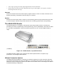


Mounting the AR400
1. Position the AR400 on the wall or shelf, ensuring 5 inches (12.7 cm) of clearance on all sides.
2. Using the pre-drilled holes at the corners of the AR400 as a guide, drill four holes in the wall or shelf
for mounting the AR400.
3. Secure the AR400 to the wall or shelf using four 1-inch long #10 screws.
Connecting Antennas to the AR400
Power off the AR400 before connecting the antennas. Never disconnect the
antennas while the AR400 is powered on or reading tags (when the yellow LED is lit).
Doing so can damage the AR400.
Do not turn on the antenna ports from a host to which antennas are not connected.
1. Attach the N-Male plug (large end) of an antenna connector cable to antenna 1.
2. Attach the DIN 1.0/2.3 jack connectors (small ends) of the cable to the TX
1
and RX
1
connectors on
the AR400.
3. Secure the cable using wire ties. Do not bend the cable.
Repeat these steps to connect antenna 2 to Tx
2
/Rx
2
, antenna 3 to TX
3
/RX
3
, and antenna 4to TX
4
/RX
4
.
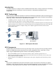
Portal Setup
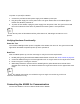
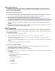
In portal situations such as dock doors, ensure the TX for an antenna on one side of the portal faces
the TX of the opposing antenna. Similarly, ensure the antennas’ respective RXs face each other, as
shown in Portal Alignment .
Antenna Pair 1
Antenna Pair 2
Figure 2-2. Portal Alignment
Powering the AR400
Connect the antennas before supplying power to the AR400.