LS 3070 Product Reference Guide Click on red text at any location in the manual to jump to the specified chapter, topic, or reference.
© 1997 SYMBOL TECHNOLOGIES, INC. All rights reserved. No part of this publication may be reproduced or used in any form, or by any electrical or mechanical means, without permission in writing from the publisher. This includes electronic or mechanical means, such as photocopying, recording, or information storage and retrieval systems. The material in this manual is for informational purposes and is subject to change without notice.
Contents About This Manual Notational Conventions . . . . . . . . . . . . . . . . . . . . . . . . . . . . . . . . . . . . . . . . . . . . . . . . . . . . . . . About-i Related Publications . . . . . . . . . . . . . . . . . . . . . . . . . . . . . . . . . . . . . . . . . . . . . . . . . . . . . . . . . . About-i Service Information . . . . . . . . . . . . . . . . . . . . . . . . . . . . . . . . . . . . . . . . . . . . . . . . . . . . . . . . . . . About-i Symbol Support Center. . . . . . . . . . . . . . . .
LS 3070XLR Extra Long Range . . . . . . . . . . . . . . . . . . . . . . . . . . . . . . . . . . . . . . . . . . . . . . . . . 3-9 LS 3070HV High Visibility . . . . . . . . . . . . . . . . . . . . . . . . . . . . . . . . . . . . . . . . . . . . . . . . . . . . 3-10 Chapter 4. Maintenance and Specifications Maintenance . . . . . . . . . . . . . . . . . . . . . . . . . . . . . . . . . . . . . . . . . . . . . . . . . . . . . . . . . . . . . . . . . . . . . 4-1 Recharging the Battery . . . . . . . . . . . . . .
Code Types . . . . . . . . . . . . . . . . . . . . . . . . . . . . . . . . . . . . . . . . . . . . . . . . . . . . . . . . . . . . . . . . . . 6-3 Code Lengths . . . . . . . . . . . . . . . . . . . . . . . . . . . . . . . . . . . . . . . . . . . . . . . . . . . . . . . . . . . . . . . . 6-3 Code 39 Full ASCII . . . . . . . . . . . . . . . . . . . . . . . . . . . . . . . . . . . . . . . . . . . . . . . . . . . . . . . . . . . 6-4 Decode Options . . . . . . . . . . . . . . . . . . . . . . . . . . . . . . . .
UPC-A Preamble . . . . . . . . . . . . . . . . . . . . . . . . . . . . . . . . . . . . . . . . . . . . . . . . . . . . . . . . . . . . . . . . UPC-E Preamble. . . . . . . . . . . . . . . . . . . . . . . . . . . . . . . . . . . . . . . . . . . . . . . . . . . . . . . . . . . . . . . . . Pause Duration . . . . . . . . . . . . . . . . . . . . . . . . . . . . . . . . . . . . . . . . . . . . . . . . . . . . . . . . . . . . . . . . . . Prefix/Suffix Values . . . . . . . . . . . . . . . . . . . . . . . . . . . . .
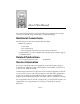
About This Manual The LS 3070 Product Reference Guide provides general instructions for setup, operation, troubleshooting, maintenance, and programming. Notational Conventions The following conventions are used in this document: • Bullets (•) indicate: - action items - lists of alternatives - lists of required steps that are not necessarily sequential • Sequential lists (e.g., those that describe step-by-step procedures) appear as numbered lists.
LS 3070 Product Reference Guide: About This Manual Note: Symbol Technologies is not responsible for any damages incurred during shipment if the approved shipping container is not used. Shipping the units improperly can possibly void the warranty. If the original shipping container was not kept, contact Symbol to have another sent to you. Symbol Support Center In the U.S.
Chapter 1 The LS 3070 Cordless Scanner The Freedom of Cordless Scanning The LS 3070 is a revolutionary, cordless approach to capturing bar coded data. The scanner communicates with your host computer through a low-power radio transmission instead of through a cable. With the LS 3070, you are free to scan and transmit without a physical cable to limit your movement, from as far away as 30 - 50 feet (9 - 15 meters), depending on your environment.
LS 3070 Product Reference Guide: The LS 3070 Cordless Scanner The LS 3070 Scanner Housed in rugged, durable plastic, the LS 3070 scanner combines accurate, aggressive bar code scanning with solid state dependability. Its ergonomic design ensures comfortable use for extended periods of time. This scanner combines premium visible laser diode (VLD) scanning performance, reading color bar codes and symbols printed on all substrates, with advanced decode and RF transceiver capabilities.
LS 3070 Product Reference Guide: The LS 3070 Cordless Scanner Rechargeable Battery Pack In the handle of the scanner, there is a rechargeable NiCad battery pack. This provides all power to the scanner during normal operation. It provides 360 mA hours, which is sufficient for normal operation during an 8-hour shift. When fully depleted, the battery module can be recharged to full charge within two hours, with the LS 3070 inserted into the RL 470 base/charger unit.
LS 3070 Product Reference Guide: The LS 3070 Cordless Scanner The Base/Charger Unit The base/charger unit has two primary functions. First, it is the base station interface that manages the flow of information from the scanner to the host device. Second, it is a charging stand which charges the scanner’s battery module (located in the handle) and also holds the scanner securely when it is not in use. An LED indicates the status of battery charging.
Chapter 2 Setup Unpacking Remove the LS 3070, the RL 470 base/charger unit, and the host interface cable from its packing and inspect each for evidence of physical damage. If any equipment was damaged in transit, call the Symbol Support Center at the number in the front matter. KEEP THE PACKING. It is the approved shipping container and should be used if you ever need to return your equipment for servicing.
LS 3070 Product Reference Guide: Setup The RL 470 base station is a charger, host interface, and — significantly — receiving station for RF transmission. Therefore, do not install the RL 470 inaccessibly under a table or buried in a desk drawer. At a minimum, mount the RL 470 on a table or desk top. For optimum RF performance, especially in difficult environments, mount the RL 470 on a wall as high as possible. But keep in mind the limits of interface cable length and charging accessibility.
LS 3070 Product Reference Guide: Setup Charging the Battery Before its first use, the LS 3070 batteries must be charged. To do so: • Connect the power supply to the power input port on the front panel of the RL 470 base/charger, shown in Figure 1-3: RL 470 Base/Charger Unit on page 1-4. • Connect the power supply to a receptacle supplying AC power of the proper voltage level.
LS 3070 Product Reference Guide: Setup Note: When setting the address of the base, you automatically set the initial frequency on which the base and the scanner communicate. In order to minimize possible interference between systems, bases which are close to each other should be assigned sequential addresses. Set the address through setting two rotary dials, located by opening a panel on the base/charger’s underside. Turn the base/charger upside down, open the panel, and notice two rotary dials.
LS 3070 Product Reference Guide: Setup Possible Base/Charger Addresses 01 02 03 04 05 06 07 08 09 0A 0B 0C 0D 0E 0F 10 11 12 13 14 15 16 17 18 19 1A 1B 1C 1D 1E 1F 20 21 22 23 24 25 26 27 28 29 2A 2B 2C 2D 2E 2F 30 31 32 33 34 35 36 37 38 39 3A 3B 3C 3D 3E 3F 40 41 42 43 44 45 46 47 48 49 4A 4B 4C 4D 4E 4F 50 51 52 53 54 55 56 57 58 59 5A 5B 5C 5D 5E 5F 60 61 62 63 64 65 66 67 68 69 6A 6B 6C 6D 6E 6F 70 71 72 73 74 75 76 77 78 79
LS 3070 Product Reference Guide: Setup • At that time, through the scanner’s contact shoe, there is an exchange of information (addressing, RF channels, etc.) between the scanner and the base/charger’s cradle. This occurs in less than a second. • After that exchange, the scanner and base/charger are paired. Successful pairing is indicated by a warble beep; failure, or unsuccessful link, is indicated by a Lo Lo Lo Lo beep.
LS 3070 Product Reference Guide: Setup Occasionally, there can be excessive interference on a channel from some other source of radio transmissions. In this case, the default channel of a system can be changed using the parameter codes for Set Transmission Frequency. If you find a particular scanner/base pair has trouble communicating over a normal operating distance, try setting different transmission frequencies to see if performance improves.
Chapter 3 Scanning with the LS 3070 1. Ready Before starting to scan bar codes for data collection, make sure: • The base station is connected to the host device. • The battery has been charged. • The scanner is paired with the base/charger. 2. Test Aim the scanner toward a bar code and press the trigger. When you press the trigger, the scanning beam is energized. 3. Scan Make sure the symbol you want to scan is within the proper scanning range. (See Decode Zones beginning on page 3-6.
LS 3070 Product Reference Guide: Scanning with the LS 3070 If the scanning attempt ends in 4 error beeps, any of these may be true: • Scanner is out of transmission range • Scanner and base/charger are not paired • Base/charger is not powered. Hold at an Angle Do not hold the scanner directly over the bar code. In this position, light can bounce back into the scanner's exit window and prevent a successful decode. Scan the Entire Symbol • Your scan beam must cross every bar and space on the symbol.
LS 3070 Product Reference Guide: Scanning with the LS 3070 Using a Long Range or High Visibility Scanner? These scanners have two-position triggers. Press the trigger to the first detent and center the “collapsed” aiming beam on the target bar code, as illustrated below. The collapsed beam helps to establish the correct scanning position. Press the trigger to the second detent, and a scan beam crosses all the bars and spaces on the bar code.
LS 3070 Product Reference Guide: Scanning with the LS 3070 Scanning Transmission Range RF Communication Errors RF communication errors occur when the scanner is out of range from the base during a scan data transmission attempt. An error is indicated by 6 beeps after a bar code is scanned, although the bar code data appears on the host display. This happens when the base receives the bar code data but the scanner did NOT get the HIF response from the base, and therefore timed out.
LS 3070 Product Reference Guide: Scanning with the LS 3070 What If ... Nothing happens when you follow the operating instructions? You should • Check that the power supply is attached to the base/charger. • Check for loose cable connections at the base/charger and host device. • Check the scanner’s battery pack. • Make sure the device is programmed to read the type of bar code you want to scan. • Check the symbol to make sure it is not defaced. • Try scanning similar symbols of the same code type.
LS 3070 Product Reference Guide: Scanning with the LS 3070 Decode Zones LS 3070 Standard Range 10 25.4 5 12.7 0 0 5 12.7 10 25.4 Front of the Scanner .0055 In. .0075 In. .020 In. Minimum Element Width .040 In. Minimum Element Width .055 In. Minimum Element Width In. Cm. 0 5 10 15 20 25 30 35 Inches 0 12.7 25.4 38.1 50.8 63.5 76.2 88.9 Cm. Distance from Front of Scanner Figure 3-1. LS 3070 Decode Zone: Depth of field as a function of minimum element width.
LS 3070 Product Reference Guide: Scanning with the LS 3070 LS 3070LR Long Range NOTE: Typical performance at 23o C (75o F) on high quality symbols. 30 76 10 25.4 Front of the Scanner 0 7.5 Mil 0 10 25.4 10 Mil 20 51 15 Mil 30 76 20 Mil 40 Mil 0 0 20 10 25 51 30 76 In. Cm. 70 Mil Reflective 40 60 102 50 152 127 70 178 80 100 203 90 254 110 305 130 366 229 120 280 144 Inches Cm 330 Distance from Front of Scanner Figure 3-2.
LS 3070 Product Reference Guide: Scanning with the LS 3070 LS 3070ALR Advanced Long Range NOTE: Typical performance at 23o C (75o F) on high quality symbols. 10 25.4 Front of the Scanner 0 0 10 25.4 15 Mil 20 51 In. Cm. 40 Mil 70 Mil Reflective 0 20 40 60 80 100 120 140 160 180 200 220 240 Inches 0 51 102 152 203 254 356 406 508 Cm 305 457 556 610 Distance from Front of Scanner Figure 3-3. LS 3070ALR Decode Zone: Depth of field as a function of minimum element width.
LS 3070 Product Reference Guide: Scanning with the LS 3070 LS 3070XLR Extra Long Range NOTE: Typical performance at 23o C (75o F) on high quality symbols. 10 25.4 Front of the Scanner 0 0 10 25.4 30 Mil 20 51 40 Mil In. Cm. 55 Mil 0 20 40 60 80 100 120 0 51 102 152 203 254 305 140 160 180 Inches 356 406 457 Cm Distance from Front of Scanner Figure 3-4. LS 3070XLR Decode Zone: Depth of field as a function of minimum element width.
LS 3070 Product Reference Guide: Scanning with the LS 3070 LS 3070HV High Visibility Front of the Scanner .0075 In. .020 In. Minimum Element Width .040 In. Minimum Element Width .055 In. Minimum Element Width 13 33 10 25.4 5 12.7 0 0 5 12.7 10 25.4 13 33 In. Cm. 0 5 10 15 20 25 30 34 Inches 0 12.7 25.4 38.1 50.8 63.5 76.2 86.4 Cm. Distance from Front of Scanner Figure 3-5. LS 3070HV Decode Zone: Depth of field as a function of minimum element width.
Chapter 4 Maintenance and Specifications Maintenance Cleaning the exit window is the only maintenance required. A dirty window may affect scanning accuracy. • Do not allow any abrasive material to touch the window. • Remove any dirt particles with a damp cloth. • Wipe the window using a tissue moistened with ammonia/water. • Do not spray water or other cleaning liquids directly into the window.
LS 3070 Product Reference Guide: Maintenance and Specifications Power Supply Connection Port Figure 4-1. Recharging the LS 3070 Changing Battery Packs You can charge battery packs on the Universal Four Slot Battery Charger so that a charged battery pack is available when needed. In this case, simply remove the depleted battery pack and replace it with a freshly charged one. User instructions are in the Universal Four-Slot Battery Charger Quick Reference Guide.
LS 3070 Product Reference Guide: Maintenance and Specifications 1. Remove Lower Handle from Scanner. Using a probe, press in the release button on the handle, as indicated at the right. With button pressed in below the outer housing, slide the battery pack out from the handle. Release Button Four Slot Charger with Charging Adapter LS 3070 Battery Pack Figure 4-2. Changing LS 3070 Battery Packs 2. Insert Charged Battery Pack in Handle.
LS 3070 Product Reference Guide: Maintenance and Specifications Charge Status LED Indications On the base/charger, there is a red LED indicator which uses flashing patterns to indicate the current charger status. The red Charge Status LED indicates the following conditions: • RED LED OFF — The scanner is not properly inserted or the battery is not functioning properly. • RED LED blinking slowly (1/8 sec. ON, 3/8 sec. OFF) — Battery charge is pending.
LS 3070 Product Reference Guide: Maintenance and Specifications Accessories Standard Accessories Part Number Description RL 470 Base/interface charger Base/Charger Cable: Cables are available for most applications. See the Electronic ProductOrdering Guide for more information.
LS 3070 Product Reference Guide: Maintenance and Specifications LS 3070 Standard Technical Specifications ITEM Power Requirements: Scanner Base/Charger DESCRIPTION 4.75 to 14 VDC; 210 mA @ 5 VDC Typical. 5 VDC ± 10% @ 190 mA Typical. 12 VDC ± 10% @ 400 mA Typical. Scan Repetition Rate Approximately 36 (± 3) scans/sec (bidirectional) Start-up Time <50 msec. from scan enable Data Acquisition Time <110 msec.
LS 3070 Product Reference Guide: Maintenance and Specifications LS 3070LR Technical Specifications ITEM Power Requirements: Scanner Base/Charger DESCRIPTION Scan Repetition Rate Start-up Time Approximately 36 (± 3) scans/sec (bidirectional) <50 msec. from scan enable Data Acquisition Time <110 msec. from scan enable Skew Tolerance ± 60° from normal Pitch Angle ± 45° from normal Decode Depth of Field See LS 3070LR Long Range on page 3-7 Minimum Element Width 0.007 in. .
LS 3070 Product Reference Guide: Maintenance and Specifications LS 3070ALR Technical Specifications ITEM Power Requirements: Scanner Base/Charger DESCRIPTION Scan Repetition Rate Start-up Time Approximately 36 (± 3) scans/sec (bidirectional) <50 msec. from scan enable Data Acquisition Time <110 msec. from scan enable Skew Tolerance ± 60° from normal Pitch Angle ± 45° from normal Decode Depth of Field See LS 3070ALR Advanced Long Range on page 3-8 Minimum Element Width 0.015 in. .
LS 3070 Product Reference Guide: Maintenance and Specifications LS 3070XLR Technical Specifications ITEM Power Requirements: Scanner Base/Charger DESCRIPTION 4.75 to 14 VDC; 210 mA @ 5 VDC Typical. 5 VDC ± 10% @ 190 mA Typical. 12 VDC ± 10% @ 400 mA Typical. Scan Repetition Rate Approximately 36 (± 3) scans/sec (bidirectional) Start-up Time <50 msec. from scan enable Data Acquisition Time <110 msec.
LS 3070 Product Reference Guide: Maintenance and Specifications LS 3070HV Technical Specifications ITEM Power Requirements: Scanner Base/Charger DESCRIPTION Scan Repetition Rate Approximately 36 (± 3) scans/sec (bidirectional) Start-up Time <50 msec. from scan enable Data Acquisition Time <110 msec. from scan enable Skew Tolerance ± 60° from normal Pitch Angle ± 45° from normal Decode Depth of Field See LS 3070HV High Visibility on page 3-10 Minimum Element Width 0.0075 in. .
Chapter 5 Interface Guide Connecting to a Host Device In most cases, connecting your LS 3070’s base station to your host terminal is a very simple operation. You need only plug the cable into your host. Typical configurations are shown on the following pages. Some POS keyboards require more intricate installation instructions. Those begin on page 5-6. We recommend that you disconnect the power supply from the base station prior to connecting or disconnecting cables.
LS 3070 Product Reference Guide: Interface Guide Connecting Base Station to a Host OCIA and OCR Terminals The OCIA or OCR port must be activated and referenced by the POS system, or no communications will take place. POS Terminal Base Station Figure 5-1. Connecting Base Station to OCIA/OCR Terminals These include: OCR IBM 3653/3683/3684, Fujitsu 7770/7880/7990/8770/9000. OCIA NCR 2151/2152/2154/2155/2157/2126/2126-1120/2950/7050/7052, Nixdorf 8812, ICL 9505/9507/9518.
LS 3070 Product Reference Guide: Interface Guide RS-232C Single Port RS-232C Device Base Station Figure 5-2. Connecting Base Station to RS-232C Single-Port Host Any of the following RS-232C (DB 25) connectors are supported: Male, TxD on pin 2 or TxD on pin 3. Female, TxD on Pin 2 or Pin 3. For other pinouts and cable types, contact the Symbol Support Center at 1-800-653-5350. RS-232C Dual Port Host System (Port 1) RS-232C Auxiliary Device (Port 2) Base Station Figure 5-3.
LS 3070 Product Reference Guide: Interface Guide IBM 4683/4684/4693/4694 IBM 4683/4 IBM 4693 IBM 4694 5B, 9B, 17 5B, 9B, 9C« 9E IBM 4683/84; 4693/94 Base Station Figure 5-4. Connecting Base Station to IBM 4683/4684/4693/4694 To connect the base station, plug the cable into the appropriate port on the rear of the IBM 4683/84, 4693/94. For the IBM 4693, port 9C (which replaces port 17 on the 4683/84) is the appropriate port for connecting the base station.
LS 3070 Product Reference Guide: Interface Guide Connecting Keyboard Wedges Terminal Base Station Keyboard Figure 5-5. Connecting Base Station to Keyboard Wedge These include: PC Keyboards IBM PC/AT/XT, PS2-30/50/55SX/60/70 and clones. Terminal Keyboards DEC VT2XX/VT3XX/4XX; HP 700/92, 2392; IBM 3178/3278/3151/316X/ 3179/3180/319X, 3278, 347X; Telex-Memorex 88, 122; Wyse 50/60/85/185/ 150.
LS 3070 Product Reference Guide: Interface Guide IBM 3683/3684 Installation Caution Install cables as described below. Failure to do so may result in hardware damage. There are four basic steps to this installation: 1. Remove the IBM 3683/84 top cover. 2. Remove the keyboard. 3. Install the cable internally or externally. 4. Replace the keyboard and top cover. First: Remove the IBM 3683/84 Top Cover 1. Set ON/OFF switch to OFF. 2. If display is integrated, disconnect the display cable). 3.
LS 3070 Product Reference Guide: Interface Guide Third: Install the Cable Internally The base station cable is installed internal to the IBM 3683/84 with the cable exiting the rear of the terminal. 1. Remove the printer assembly as follows: • Disconnect the printer ground strap (slide on connector) from the right side of the printer, as shown in Figure 5-7). • Slide the two printer locking tabs (black plastic) toward the front of the register while pressing downward, as shown in Figure 5-8.
LS 3070 Product Reference Guide: Interface Guide Fourth: Replace the Keyboard and Top Cover 1. Replace the keyboard down into the retaining glides. 2. Replace the top cover as follows: • Replace the display cable if display is integrated. • Hold the cover so that rear slots fit into retaining tabs. • Lower the cover at front to engage the front side latches. You can now attach your scanner and peripheral devices. Figure 5-6.
LS 3070 Product Reference Guide: Interface Guide Connector Printer Ground Strap Figure 5-7. Disconnecting Cable from Connector Locking Tab Figure 5-8.
LS 3070 Product Reference Guide: Interface Guide Figure 5-9. Cable Figure 5-10.
LS 3070 Product Reference Guide: Interface Guide Figure 5-11. Connecting J2 to J16 Figure 5-12.
LS 3070 Product Reference Guide: Interface Guide IBM 3653 Installation 1. Be sure the IBM 3653 terminal is powered-down. Open the door over the ribbon cartridge as shown in Figure 5-13. 2. Loosen the right side panel screw (see Figure 5-13). Grasp the right panel at top of the rear corner; pull out to the side and push back to remove the panel. 3. Loosen the two screws behind the top of the keyboard cover. Lift and remove the keyboard cover. See Figure 5-14. 4.
LS 3070 Product Reference Guide: Interface Guide 11. Remove the protective foam from the register end of the base station Ycable, and insert into the cable assembly. Place the assembly near the bottom of the register behind the keyboard. 12. Install the keyboard connector, as shown in Figure 5-19. Secure with the tie wrap that doesn't have a mounting hole. 13. Locate the brass plate behind the card cage and remove the front left screw. Install tie wrap between the screw and plate.
LS 3070 Product Reference Guide: Interface Guide Screws Figure 5-14. Removing Keyboard Cover Figure 5-15.
LS 3070 Product Reference Guide: Interface Guide Figure 5-16. Opening Card Cage Figure 5-17.
LS 3070 Product Reference Guide: Interface Guide Figure 5-18. Voltage Adjustment Hole Figure 5-19.
LS 3070 Product Reference Guide: Interface Guide NCR 280 Installation 1. Ensure that the NCR 280 is powered down and unplugged. Open the door on the top, left-hand side and remove the two screws which fasten the steel plate to the terminal cover. Slide the steel plate to the left to remove. 2. Remove the two round head screws from the back of the terminal. Be sure the doors on the left and right side of the terminal are open and that there are no keys inserted in the locks on the front.
LS 3070 Product Reference Guide: Interface Guide 12. Cut a 1-in. diameter semicircle at the bottom left of the terminal cover, approximately 6 1/2 in. from the back of the unit, so that when the cover is replaced, this opening fits over the cable. Be sure to file down all sharp edges. 13. Replace the terminal cover making sure that cable fits into the opening; secure the two screws at the back of the terminal. Replace the steel plate to the terminal cover and secure.
LS 3070 Product Reference Guide: Interface Guide 5. Locate the end of the RL 470 base station cable that branches into a “Y”. Slide that end under the board assembly inside the register. Leave enough slack to make the connection required in the next few steps. 6. Mate the RL 470 base station cable “Y” branch ending in a 2 x13 female boxtype connector to P1 on the K8 T-board. Connector P1 is the middle connector on the T-Board. Note: Connector position 1 of the mating pair is keyed. 7.
LS 3070 Product Reference Guide: Interface Guide NCR 2152 Installation 1. Switch off the NCR 2152. Remove the two large, pan head screws from the front of the terminal to allow the top section to open up. Use the two hood support rods located to the sides of the housing to support the top section. 2. Locate the large steel plate covering the printed circuit board assembly. Remove the two screws on the right-hand side of the plate.
LS 3070 Product Reference Guide: Interface Guide NCR 2154/2155 Installation 1. Power-down the NCR 2154/2155 POS terminal. 2. Remove the keyboard by grasping the keyboard cover at its corners and lifting upward. 3. Remove the cable connecting the keyboard to the terminal’s main PC board. 4. Install the LL 500 cable in place of the keyboard cable just removed.
LS 3070 Product Reference Guide: Interface Guide Fujitsu 9000 Installation 1. Switch-off the Fujitsu 9000, and disconnect the power. Push down on the keyboard release latch below the keyboard. Pull the keyboard forward, lift and remove 2. Press down the printer release tab. Push the printer back and remove. Press down the display release tab. Push the display back and remove. 3. Remove the four screws securing the top plate to the chassis. Carefully lift the top plate.
LS 3070 Product Reference Guide: Interface Guide Interfaces Select the appropriate interface cable assembly for your host system.
LS 3070 Product Reference Guide: Interface Guide Host Type NCR 280 NCR 2126-1120 NCR 2151 NCR 2152 NCR 2152/2257/2950 NCR 2154/2155/2157/7050 NCR 7052 NCR 7052 Wedge OCIA Wedge Wedge OCIA OCIA OCIA Wedge IK-0700 IK-1004 IK-0600 IK-0500 IK-1001 IK-1002 IK-1000 IK-0402 Nixdorf 8812 OCIA IK-1003 Telex Memorex 88, 122 Wedge IK-0400 Wyse 60, 85, 150, 150+, 185 Wedge IK-1300 5-24 Interface P/N
Chapter 6 Programming Programming Overview Before programming, follow the instructions in the Chapter 2: Setup and Chapter 5: Interface Guide. Programming occurs through use of bar code menus. Not all parameters, however, apply to your specific host. For example, if you have an OCIA terminal, RS-232C parameters such as baud rate and parity will not apply. Simply ignore those parameters not designed for your application.
LS 3070 Product Reference Guide: Programming Scanning Sequence Examples In most cases you need only scan one bar code to set a specific parameter. For example, if you want to set the baud rate to 9600, simply scan the 9600 bar code listed under Baud Rate. The base station will issue a warble tone, signifying a successful parameter entry. If you want to add or change prefixes and suffixes or customize the data transmission format, you will have to scan several bar codes.
LS 3070 Product Reference Guide: Programming Parameter Descriptions Set Parameter Defaults Scanning the SET DEFAULT bar code returns all parameters to the values listed in the Default Table beginning on page 6-28. Host Interface Code Each Interface Cable Assembly defaults to a given host. These assemblies, their corresponding defaults, and additional bar codes begin in Chapter 7: Parameter Menus.
LS 3070 Product Reference Guide: Programming One Discrete Length - This option will allow you to decode only those codes containing a selected length. For example, if you select D 2 of 5 One Discrete Length, then scan 1, 4, the only D 2 of 5 codes decoded will be those containing 14 characters Two Discrete Lengths - This option will allow you to decode only those codes containing two selected lengths.
LS 3070 Product Reference Guide: Programming Decode Options Transmit UPC-E/UPC-A Check Digit Select if decoded UPC symbols are transmitted with or without a check digit. Convert UPC-E To UPC-A Use this parameter to convert UPC-E (zero suppressed) decoded data to UPCA format before transmission. After conversion, data will follow UPC format and be affected by UPC-A programming selections (e.g., Preamble, Check Digit).
LS 3070 Product Reference Guide: Programming Code 39 Check Digit When enabled, this parameter checks the integrity of a Code 39 symbol to ensure it complies with a modulo 43 check digit algorithm. ITF-14/EAN-13 Conversion If your terminal supports EAN-13, this feature converts a 14 character I 2 of 5 code into EAN-13, and transmits to the host as EAN-13.
LS 3070 Product Reference Guide: Programming Beeper Volume Select degree of volume — high or low. Beep After Good Decode Determine if the unit beeper will sound during normal scanning. Usually it is desirable to operate the unit with the beeper enabled. In all cases, the beeper operates during parameter menu scanning and indicates error conditions. See Beeper Definitions beginning on page 6-24. UPC/EAN Security Level The LS 3070 offers four levels of decode security for UPC/EAN bar codes.
LS 3070 Product Reference Guide: Programming Decode Redundancy Use this parameter to indicate whether the scanner must read a bar code one time (LEVEL 1), two times (LEVEL 2), or three times (LEVEL 3) before decoding it. A higher level of redundancy ensures the accuracy of a decode in, for example, poor quality symbols. UPC-A and -E Preamble Three options are given for the lead-in characters of decoded UPC-A or UPCE symbols transmitted to the host device.
LS 3070 Product Reference Guide: Programming Data Transmission Formats Magstripe Data Transmission Format Magstripe data format options are open for user determination with the specific application.
LS 3070 Product Reference Guide: Programming Scan Data Transmission Format Scan data format options can be selected by the user. The following are standard selections: • Standard: • Option 1: • Option 2: • Option 3: = scanned bar code data and as selected by the user Laser Control Laser On Timeout The maximum time the laser will remain on or decode processing will continue during a trigger pull.
LS 3070 Product Reference Guide: Programming RS-232C Options Baud Rate Baud rate is the number of bits of data transmitted per second. The scanner's baud rate setting should match the data rate setting of the host device. If not, data may not reach the host device or may reach it in distorted form. Parity A parity check bit is the most significant bit of each ASCII coded character.
LS 3070 Product Reference Guide: Programming • When the CTS line is negated, the base asserts the RTS line and waits for one second for the host to assert CTS. When the host asserts CTS, data is transmitted. • When data transmission is complete, the base will negate RTS 10 msec after sending the last character. • The host should respond by negating CTS. The base will check for a negated CTS upon the next transmission of data. During the transmission of data, the CTS line should be asserted.
LS 3070 Product Reference Guide: Programming Software Handshaking This parameter offers control of the data transmission process. It may be used instead of, but not in conjunction with, hardware handshaking. The base station also provides four software handshaking options: NONE, ENQ, ACK/ NAK, and ACK/NAK with ENQ. These options may be combined, for example ACK/NAK with ENQ. Refer to the chart following the parameter description.
LS 3070 Product Reference Guide: Programming When you select the wait for ENQ option, the base station waits for an ENQ, Enquire character, from the host before it transmits data; otherwise the unit transmits data without waiting for an ENQ character from the host. With ENQ enabled, the base station must receive an ENQ from the host within a 2 second period after the last activity or 4 short beeps are sounded to indicate a transmission error; the unit is now ready to scan again.
LS 3070 Product Reference Guide: Programming Serial Response Timeout This parameter determines the maximum period allowed to elapse before the base station assumes end of transmission. The delay period can range from 0 to 9.9 seconds. Stop Bit Select The stop bit(s) at the end of each transmitted character marks the end of transmission of one character and prepares the receiving device for the next character in the serial data stream.
LS 3070 Product Reference Guide: Programming Intercharacter Delay Select the intercharacter delay option matching host device requirements. The intercharacter delay gives the host system time to service its receiver and perform other tasks between characters. Select from no delay to a 99 msec delay between the transmission of each character. Transmit Code ID Character A code ID character identifies the code type of a scanned bar code.
LS 3070 Product Reference Guide: Programming OCIA Transmit Timeout When connected to an OCIA terminal, the RL 470 base/interface will attempt to transmit the data to the host. If the host is not prepared to accept data at that time (i.e., the host data buffer may be full), the RL 470 will try to retransmit the data for up to 3 seconds. If transmission is not successful, the data will be discarded, and the RL 470 will issue a transmission error.
LS 3070 Product Reference Guide: Programming National Keyboard Types Use this parameter to set the national character type for keyboard characters. Selections include U.S. English, French, German, French International, Spanish, Italian, Swedish, and U.K. English. The following terminals do not support Italian or French International but do support the other six options: IBM 3680, 316X, 319X; HP 700/92, 2392; Telex 122; Wyse 50, 60, 160.
LS 3070 Product Reference Guide: Programming Table 6-1. Hosts Supported by Industrial Scanners Host Interface U.S. U.K. Fr. Ger. Spn. Swe. Ital. Fr. In.
LS 3070 Product Reference Guide: Programming Set Transmission Frequency Use this parameter to set an initial transmission frequency to avoid interference on the default channel (channel 50). During operation, the transmission channel changes automatically whenever interference is encountered 80% of the time or more over a continuous five-minute period. The selected frequency channel must be between 01 and 82.
LS 3070 Product Reference Guide: Programming Parameter Selections Supported features for each host type. Table 6-2.
LS 3070 Product Reference Guide: Programming Table 6-2. Host Supported Parameters Decode Parameters RS-232C IBM 4683* OCIA OCR Keyboard Wedge Decode Redundancy X X X X X EAN Zero Extend X X X X X Hardware Handshaking X Host Interface Code X X X X X X X X X IBM 468X/9X Mgstrpe Comm. Ignore Unknown Chars.
LS 3070 Product Reference Guide: Programming Table 6-2. Host Supported Parameters Decode Parameters RS-232C IBM 4683* OCIA OCR Keyboard Wedge Scan Suffix X X X X X Serial Response Time-out X Software Handshaking X Transmit AIM Code ID X X X X X Transmit Code ID Chars.
LS 3070 Product Reference Guide: Programming Beeper Definitions Standard Use Beeper Sequence Indication 1 Beep - short high tone A bar code symbol, or magstripe data was decoded (if decode beeper is enabled). 2 Beeps - long high tone Mis-match between the selected host and the interface cable. 4 Beeps - long high tone This signifies either a host interface error or a format or transmission error in the magnetic stripe card or in a scanned symbol. In that case, the data is ignored.
LS 3070 Product Reference Guide: Programming Parameter Menu Scanning Beeper Sequence Indication 1 Beep - short high tone Correct entry scanned or correct menu sequence performed. 1 Beep - lo/hi tone Input error, incorrect bar code or CANCEL scanned, wrong entry, incorrect bar code programming sequence; remain in program mode. 1 Beep - hi/lo tone Keyboard parameter selected. Enter value using bar code keypad. 1 Beep - hi/lo/hi/lo tone Successful program exit with change in the parameter setting.
LS 3070 Product Reference Guide: Programming Code 39 Buffering While there is data in the transmission buffer, deleting Code 39 buffering capability via the parameter menu is not allowed. To allow disabling of Code 39 buffering, first force the buffer transmission (see Transmit Buffer on page 6-27) or clear the buffer. Buffer Data To buffer data, Code 39 buffering must be enabled, and a symbol must be read with a space immediately following the start pattern.
LS 3070 Product Reference Guide: Programming Transmit Buffer To transmit the buffer, read a symbol containing either the first or second condition: 1. Only a start character, a plus (+), and a stop character. • The unit signals that the transmission buffer has been sent (a hi/lo beep). • Unit sends the buffer. • Unit clears the buffer. 2. A Code 39 bar code with leading character other than a space. • The unit signals a good decode and buffering of that decode has occurred by giving a hi/lo beep.
LS 3070 Product Reference Guide: Programming Default Table Table 6-3.
LS 3070 Product Reference Guide: Programming Table 6-3. Defaults Parameter Default Scan Data Transmission Format Data as is Laser Control: Laser On Time-out 3 Sec RS-232C Options Baud Rate Parity Check Parity Hardware Handshaking Software Handshaking Serial Response Time-out Stop Bit Select ASCII Data Format RTS Line State 9600 Odd Enabled None None 2.
LS 3070 Product Reference Guide: Programming ** Prefix/Suffix values only apply when the selected transmission format uses them. For example, if you select the default setting for Scan Data Transmission Format (Data As Is), any prefix or suffix selected is not recognized, since the format requires neither.
LS 3070 Product Reference Guide: Programming Terminal Specific RS-232C Defaults Two RS-232C hosts are set up with their own parameter default settings. Selecting the ICL or Nixdorf RS-232C terminal will set the defaults listed below. These defaults take precedence over standard defaults. So, if you’ve selected Nixdorf RS-232C, then select the standard defaults, the Nixdorf defaults will still take precedence. Table 6-4.
LS 3070 Product Reference Guide: Programming Table 6-4.
Chapter 7 Parameter Menus While the last section provided descriptions of all parameter options and other programming information, this one provides the bar codes to do the actual programming.
LS 3070 Product Reference Guide: Programming Set Default Parameter Defaults are those listed in the Default Table beginning on page 6-28.
LS 3070 Product Reference Guide: Programming Host Interface To select a host interface: 1. Locate the type of interface from the list below. 2. Scan the corresponding bar code from those on the following pages.
LS 3070 Product Reference Guide: Programming Note: In some cases, two bar codes may correspond to one interface type; this happens when different software revisions exist for the same host type. If there are two bar codes for your host type, try the first bar code; if that does not work, then try the second one.
LS 3070 Product Reference Guide: Programming Four Options for Dual Port RS-232: Dual Port RS-232: Transmit and Receive from Port 1. Dual Port RS-232: Transmit to Ports 1 and 2 — Receive from Port 1. Dual Port RS-232: Transmit and Receive from Port 2. Dual Port RS-232: Transmit to Ports 1 and 2 — Receive from Port 2.
LS 3070 Product Reference Guide: Programming IBM PC/AT, IBM PS2-50/55SX/60/70/80 and Clones IBM PC/XT And Clones IBM PS2-30 and Clones IBM 3653 Keyboard Wedge 7-6
LS 3070 Product Reference Guide: Programming IBM 3683/3684 Calc 35 Keyboard Wedge IBM 3683/3684 Calc 48 Keyboard Wedge IBM 3683/3684 Calc 116 Keyboard Wedge 7-7
LS 3070 Product Reference Guide: Programming IBM 3683/3684 Tel 35 Keyboard Wedge IBM 3683/3684 Tel 48 Keyboard Wedge IBM 3683/3684 Tel 116 Keyboard Wedge 7-8
LS 3070 Product Reference Guide: Programming NCR 2151 (Tel) Keyboard Wedge NCR 2151 (Calc) Keyboard Wedge NCR 2152 (Tel) Keyboard Wedge NCR 2152 (Calc) Keyboard Wedge 7-9
LS 3070 Product Reference Guide: Programming NCR 280 Keyboard Wedge NCR 255/2152/2154/2155, NCR 2126-1120 NCR 2157/2257/7050, NCR “S” 7052 OCIA NCR 7052 Keyboard Wedge NCR “F” 7052 OCIA 7-10
LS 3070 Product Reference Guide: Programming NCR “S” 2950 OCIA Nixdorf 8812 OCIA ICL 9505/9507/9518/9520 OCIA Spectra Physics OCIA 7-11
LS 3070 Product Reference Guide: Programming IBM 4683/4684 Port 5B 4693 IBM 4683/4684 Port 9B 4693 IBM 4683/4684 Port 17 IBM 3653/3683/3684 OCR 7-12
LS 3070 Product Reference Guide: Programming Fujitsu 7770/7880/7990/ 8770/9000 OCR HP 239X HP 700-9X DEC VT 220/320 DEC VT 420 7-13
LS 3070 Product Reference Guide: Programming IBM 3178 IBM 3278 IBM 319X/347X/348X, Telex Memorex 122 IBM 3151/316X IBM 3179/3180 7-14
LS 3070 Product Reference Guide: Programming IBM 3180 (Later Software Revision) — See Note, p. 7-4.
LS 3070 Product Reference Guide: Programming Wyse 60 (PC Keybd) Wyse 150 / Wyse 150+ Wyse 60/150 (ANSI 101 Keybd) Wyse 85/150+/185 (ANSI 105 Keybd) HP 2392 (Later Software Revision) — See Note, p. 7-4.
LS 3070 Product Reference Guide: Programming Code Type Add or delete specific code types by scanning the appropriate bar code(s).
LS 3070 Product Reference Guide: Programming ADD CODE 39 DELETE CODE 39 ADD CODE 39 FULL ASCII* DELETE CODE 39 FULL ASCII* ADD UPC/EAN *Adding or deleting Code 39 Full ASCII only has an effect when Code 39 has been selected.
LS 3070 Product Reference Guide: Programming DELETE UPC/EAN ADD CODE 128 DELETE CODE 128 ADD EAN 128 DELETE EAN 128 7-19
LS 3070 Product Reference Guide: Programming ADD D 2 of 5 DELETE D 2 of 5 ADD I 2 of 5 DELETE I 2 of 5 7-20
LS 3070 Product Reference Guide: Programming ADD CODABAR DELETE CODABAR ADD MSI Plessey DELETE MSI Plessey 7-21
LS 3070 Product Reference Guide: Programming Code Lengths To select two lengths for each code type: 1. Scan the desired option. 2. Scan two bar codes on page 7-27 - page 7-28 for each desired length. For example, for a length of “12”, scan “1” then “2”. For a length of “3”, scan “0”, then “3”. You must always scan two bar codes for each length. 3. If you make an error, or wish to change your selection, scan CANCEL on page 7-28.
LS 3070 Product Reference Guide: Programming CODE 128 - ANY LENGTH CODABAR - ANY LENGTH CODABAR - LENGTH WITHIN RANGE CODABAR 1 - DISCRETE LENGTH CODABAR - 2 DISCRETE LENGTHS 7-23
LS 3070 Product Reference Guide: Programming I 2 OF 5 - ANY LENGTH* I 2 OF 5 - LENGTH WITHIN RANGE I 2 OF 5 - 1 DISCRETE LENGTH I 2 OF 5 - 2 DISCRETE LENGTHS * Choosing I 2 of 5 Any Length may lead to misreads for I 2 of 5 and UPC codes.
LS 3070 Product Reference Guide: Programming D 2 OF 5 - ANY LENGTH D 2 OF 5 - LENGTH WITHIN RANGE D 2 OF 5 - 1 DISCRETE LENGTH D 2 OF 5 - 2 DISCRETE LENGTHS 7-25
LS 3070 Product Reference Guide: Programming MSI Plessey - ANY LENGTH MSI Plessey - LENGTH WITHIN RANGE MSI Plessey - 1 DISCRETE LENGTH MSI Plessey - 2 DISCRETE LENGTHS 7-26
LS 3070 Product Reference Guide: Programming 0 1 2 3 4 5 7-27
LS 3070 Product Reference Guide: Programming 6 7 8 9 CANCEL 7-28
LS 3070 Product Reference Guide: Programming Decode Options Enable or disable a specific decode option by scanning the appropriate bar code.
LS 3070 Product Reference Guide: Programming .
LS 3070 Product Reference Guide: Programming DECODE UPC/EAN SUPPLEMENTALS IGNORE UPC/EAN SUPPLEMENTALS AUTODISCRIMINATE UPC/EAN SUPPLEMEN- ENABLE EAN ZERO EXTEND DISABLE EAN ZERO EXTEND 7-31
LS 3070 Product Reference Guide: Programming TRANSMIT “NO DECODED MESSAGE DO NOT TRANSMIT “NO DECODE” MESSAGE ITF14/EAN-13 CONVERSION ENABLED ITF14/EAN-13 CONVERSION DISABLED 7-32
LS 3070 Product Reference Guide: Programming BUFFER CODE 39 DO NOT BUFFER CODE 39 VERIFY CODE 39 CHECK DIGIT DO NOT VERIFY CODE 39 CHECK DIGIT 7-33
LS 3070 Product Reference Guide: Programming BI-DIRECTIONAL REDUNDANCY ENABLED BI-DIRECITONAL REDUNDANCY DISABLED BEEP AFTER GOOD DECODE DO NOT BEEP AFTER GOOD DECODE 7-34
LS 3070 Product Reference Guide: Programming LOW BEEPER VOLUME HIGH BEEPER VOLUME UPC/EAN SECURITY LEVEL 0 UPC/EAN SECURITY LEVEL 1 UPC/EAN SECURITY LEVEL 2 7-35
LS 3070 Product Reference Guide: Programming UPC/EAN SECURITY LEVEL 3 DECODE REDUNDANCY 1 DECODE REDUNDANCY 2 DECODE REDUNDANCY 3 7-36
LS 3070 Product Reference Guide: Programming UPC-A Preamble Select one option for UPC-A preamble by scanning the appropriate bar code.
LS 3070 Product Reference Guide: Programming UPC-E Preamble Select one option for UPC-E preamble by scanning the appropriate bar code.
LS 3070 Product Reference Guide: Programming Pause Duration To set a pause duration: 1. Scan the PAUSE DURATION bar code below. 2. Scan two bar codes on the next two pages which represent the desired pause. You must always scan two bar codes. 3. If you make an error, or wish to change your selection, scan CANCEL.
LS 3070 Product Reference Guide: Programming 0 1 2 3 4 5 7-40
LS 3070 Product Reference Guide: Programming 6 7 8 9 CANCEL 7-41
LS 3070 Product Reference Guide: Programming Prefix/Suffix Values Note: These values will also be used for Advanced Data Formatting programming. See the Advanced Programmer’s Guide for details. To set a PREFIX/SUFFIX value: 1. Scan the option bar code you wish to set. 2. Scan four bar codes from page 7-44 - page 7-45 which correspond to the ASCII value or keystroke you wish to assign (see ASCII Table beginning on page 8-1). The ENTER key is the default for all options. 3.
LS 3070 Product Reference Guide: Programming SCAN SUFFIX (VALUE 1) SCAN PREFIX (VALUE 2) MAGSTRIPE SUFFIX (VALUE 3) MAGSTRIPE PREFIX (VALUE 4) 7-43
LS 3070 Product Reference Guide: Programming 0 1 2 3 4 5 7-44
LS 3070 Product Reference Guide: Programming 6 7 8 9 CANCEL 7-45
LS 3070 Product Reference Guide: Programming Data Transmission Formats To select a data transmission format: 1. Scan the SCAN OPTIONS or MAGSTRIPE OPTIONS bar code. 2. Scan the bar code corresponding to the desired converted data format. 3. Scan ENTER. 4. If you make a mistake, scan CANCEL, or you wish to erase the last entered format, or all formats, scan the appropriate bar code from page 7-52. Note: RS-232C hosts will treat the extended keypad default suffix (7013) as Enter.
LS 3070 Product Reference Guide: Programming ENTER 7-47
LS 3070 Product Reference Guide: Programming Magstripe Options MAGSTRIPE OPTIONS DATA AS ON CARD 7-48
LS 3070 Product Reference Guide: Programming 7-49
LS 3070 Product Reference Guide: Programming 7-50
LS 3070 Product Reference Guide: Programming 7-51
LS 3070 Product Reference Guide: Programming ERASE ALL FORMATS ERASE LAST ENTERED FORMAT CANCEL ENTER 7-52
LS 3070 Product Reference Guide: Programming Laser Control To select a laser-on timeout: 1. Scan the LASER ON TIMEOUT bar code below. 2. Scan two bar codes from the next two pages which correspond to the desired time. 3. If you make an error, or wish to change your selection, scan CANCEL.
LS 3070 Product Reference Guide: Programming 0 1 2 3 4 5 7-54
LS 3070 Product Reference Guide: Programming 6 7 8 9 CANCEL 7-55
LS 3070 Product Reference Guide: Programming Baud Rate Set the baud rate for RS-232C transmission.
LS 3070 Product Reference Guide: Programming .
LS 3070 Product Reference Guide: Programming Parity Set the type of parity for RS-232C transmission.
LS 3070 Product Reference Guide: Programming Check Parity Select whether or not to check parity for RS-232C transmissions.
LS 3070 Product Reference Guide: Programming Hardware Handshaking Select the type of RS-232C hardware handshaking protocol.
LS 3070 Product Reference Guide: Programming Software Handshaking Select the type of RS-232C software handshaking protocol.
LS 3070 Product Reference Guide: Programming Serial Response Timeout To set a serial (RS-232C) response timeout: 1. Scan the SERIAL RESPONSE TIMEOUT bar code below. 2. Scan two bar codes from the next two pages which represent the desired timeout. You must always scan two bar codes. 3. If you make an error, or wish to change your selection, scan CANCEL.
LS 3070 Product Reference Guide: Programming 0 1 2 3 4 5 7-63
LS 3070 Product Reference Guide: Programming 6 7 8 9 CANCEL 7-64
LS 3070 Product Reference Guide: Programming Stop Bit Select Select the desired number of stop bits for RS-232C communications.
LS 3070 Product Reference Guide: Programming ASCII Data Format Select either 7-bit or 8-bit ASCII format for RS-232C communications.
LS 3070 Product Reference Guide: Programming RTS Line State Select the desired option.
LS 3070 Product Reference Guide: Programming Intercharacter Delay To set a host communications intercharacter delay: 1. Scan the INTERCHARACTER DELAY bar code below. 2. Scan two bar codes from the next two pages which represent the desired delay. You must always scan two bar codes. 3. If you make an error, or wish to change your selection, scan CANCEL.
LS 3070 Product Reference Guide: Programming 0 1 2 3 4 5 7-69
LS 3070 Product Reference Guide: Programming 6 7 8 9 CANCEL 7-70
LS 3070 Product Reference Guide: Programming Transmit Code ID Character Select whether to enable or disable this parameter.
LS 3070 Product Reference Guide: Programming Transmit AIM Code ID Select whether to enable or disable this parameter. This parameter is only valid when Transmit Code ID Character is enabled.
LS 3070 Product Reference Guide: Programming Ignore Unknown Characters Scan the appropriate bar code to enable or disable this parameter.
LS 3070 Product Reference Guide: Programming OCIA Clock Polarity Select whether the OCIA clock pulse polarity will be rising or falling.
LS 3070 Product Reference Guide: Programming OCIA Transmit Timeout To set an OCIA Transmit Timeout 1. Scan the OCIA TRANSMIT TIMEOUT bar code below. 2. Scan two bar codes from the next two pages which represent the desired timeout - Between 3 and 30 seconds. You must always scan two bar codes. For a timeout less than 10 seconds, scan a leading “0”. 3. If you make an error, or wish to change your selection, scan CANCEL.
LS 3070 Product Reference Guide: Programming 0 1 2 3 4 5 7-76
LS 3070 Product Reference Guide: Programming 6 7 8 9 CANCEL 7-77
LS 3070 Product Reference Guide: Programming NCR 2152 Fast Transmit This selects the data transmission speed of the NCR 2152 POS terminal. Depending on the version of NCR 2152, selecting this option may increase the possibility of lost or mis-transmitted data. Scan the appropriate bar code to enable or disable this parameter.
LS 3070 Product Reference Guide: Programming IBM 4683 Magstripe Communications Select whether to enable or disable IBM 4683/84 magstripe communications.
LS 3070 Product Reference Guide: Programming International Keypad Emulation Select whether to enable or disable this parameter. Used only with IBM AT/XT/PS2.
LS 3070 Product Reference Guide: Programming International Keypad Emulation Fast Transmit Select whether to enable or disable this parameter. Used only with IBM AT/XT/PS2, and with International Keyboard Emulation enabled.
LS 3070 Product Reference Guide: Programming National Keyboard Types Select National Type for the keyboard. U.S.
LS 3070 Product Reference Guide: Programming Spanish Italian Swedish U.K.
LS 3070 Product Reference Guide: Programming Set Transmission Frequency All Countries Except France To set the initial channel in all countries except France: 1. Scan the SELECT CHANNEL NUMBER bar code below. 2. Scan two numeric keypad bar codes to set the two-digit channel number, which must be between 02 - 81. SELECT CHANNEL NUMBER (02-81): ALL COUNTRIES EXCLUDING FRANCE France To set the initial channel in France: 1. Scan the SELECT CHANNEL NUMBER bar code below. 2.
LS 3070 Product Reference Guide: Programming 0 1 2 3 4 5 7-85
LS 3070 Product Reference Guide: Programming 6 7 8 9 CANCEL 7-86
LS 3070 Product Reference Guide: Programming Wait for Host Interface Response Time Programming this parameter overrides the automatically set wait for host timeout value. Conversely, programming a value of zero enables the automatic wait for host response timeout calculation feature. To program the waiting period for the host’s acknowledgement of data reception: 1. Scan the WAIT FOR HOST INTERFACE RESPONSE TIME bar code. 2.
LS 3070 Product Reference Guide: Programming 0 1 2 3 4 5 7-88
LS 3070 Product Reference Guide: Programming 6 7 8 9 CANCEL 7-89
LS 3070 Product Reference Guide: Programming Reserved For Future Use ITEM 1 ENABLE ITEM 1 DISABLE ITEM 2 ENABLE ITEM 2 DISABLE 7-90
LS 3070 Product Reference Guide: Programming ITEM 3 ENABLE ITEM 3 DISABLE ITEM 4 ENABLE ITEM 4 DISABLE 7-91
LS 3070 Product Reference Guide: Programming ITEM 5 ENABLE ITEM 5 DISABLE ITEM 6 ENABLE ITEM 6 DISABLE 7-92
LS 3070 Product Reference Guide: Programming ITEM 7 ENABLE ITEM 7 DISABLE ITEM 8 ENABLE ITEM 8 DISABLE 7-93
LS 3070 Product Reference Guide: Programming APPLICATIONS VALUE 0 TO 255 ENTER 3-DIGIT NUMBER FROM NEXT 2 PAGES 7-94
LS 3070 Product Reference Guide: Programming 0 1 2 3 4 5 7-95
LS 3070 Product Reference Guide: Programming 6 7 8 9 CANCEL 7-96
LS 3070 Product Reference Guide: Programming Pairing PAIR 7-97
Chapter 8 Keyboard Maps ASCII Table The following values can be assigned as prefixes or suffixes for data transmission. Not all options are available on every keyboard. Refer to your own keyboard or Keyboard Identifier Maps on page 8-5 for pertinent keystrokes. ASCII Value 1000 1001 1002 1003 1004 1005 1006 1007 1008 1009 1010 1011 1012 1013 1014 1015 1016 1017 1018 1019 1020 1021 1022 1023 1024 1025 1026 Full ASCII Code 39 Encode Char.
LS 3070 Product Reference Guide: Keyboard Maps ASCII Value 11053 1054 1057 1056 1057 1058 1059 1060 1061 1062 1063 1064 1065 1066 1067 1068 1069 1070 1071 1072 1073 1074 1075 1076 1077 1078 1079 1080 1081 1082 1083 1084 1085 1086 1087 1088 1089 1090 Full ASCII Code 39 Encode Char.
LS 3070 Product Reference Guide: Keyboard Maps ALT Keys 2064 2065 2066 2067 2068 2069 2070 2071 2072 2073 2074 2075 2076 2077 2078 2079 2080 2081 2082 2083 2084 2085 2086 2087 2088 2089 2090 2091 2092 2093 2094 2095 Keystroke ALT 2 ALT A ALT B ALT C ALT D ALT E ALT F ALT G ALT H ALT I ALT J ALT K ALT L ALT M ALT N ALT O ALT P ALT Q ALT R ALT S ALT T ALT U ALT V ALT W ALT X ALT Y ALT Z ALT [ ALT \ ALT ] ALT 6 ALT - Misc.
LS 3070 Product Reference Guide: Keyboard Maps F Keys 5012 5013 5014 5015 5016 5017 5018 5019 5020 5021 5022 5023 5024 5025 5026 5027 5028 5029 5030 5031 5032 5033 5034 5035 5036 5037 5038 5039 Keystroke F 12 F 13 F 14 F 15 F 16 F 17 F 18 F 19 F 20 F 21 F 22 F 23 F 24 F 25 F 26 F 27 F 28 F 29 F 30 F 31 F 32 F 33 F 34 F 35 F 36 F 37 F 38 F 39 Numeric Keypad 6042 6043 6044 6045 6046 6047 6048 6049 6050 6051 6052 6053 6054 6055 6056 6057 6058 6059 6060 Keystroke * + Undefined .
LS 3070 Product Reference Guide: Keyboard Maps Keyboard Identifier Maps 5001 5002 5003 5004 7008 7014 7009 7012 7003 7004 7006 7013 5005 5006 5007 5008 5009 5010 7002 7011 IBM PC/XT and Clones 5001 5002 5003 5004 7008 7009 7014 7012 7003 7013 5005 5006 5007 5008 7004 5009 5010 7011 IBM PC/AT and Clones 8-5 7002
LS 3070 Product Reference Guide: Keyboard Maps 4013 4014 4015 4016 4001 4002 4003 4004 3003 3005 4017 4018 4019 4020 4021 4022 4005 4006 4007 4008 4009 4023 4024 4010 4011 4012 7008 3004 3006 7009 3001 3002 7005 6042 6043 6044 6047 7019 7011 6055 6056 6057 7006 7015 6052 6053 6054 6045 7012 7018 6049 6050 6051 7003 6048 6046 6058 7002 7004 3007 3008 6059 3009 3010 3011 3012 7017 7001 7013 IBM 3179 IBM 347X IBM 3180 IBM 319X Telex 122 NORMAL CNTRL 7014 5001 5002 5003 5
LS 3070 Product Reference Guide: Keyboard Maps 7014 5001 5002 5003 5004 5005 5006 5007 5008 5009 5010 5011 5012 7010 7007 7001 7011 7012 7003 6042 6043 6044 6047 7002 7019 7005 6055 6056 6057 7006 6052 6053 6054 6045 6049 6050 6051 7008 7009 6059 1013 7015 6058 7004 7017 7013* 7016 7018 6048 6046 *3001 for IBM 3151 IBM 3151 5001 5002 5003 5004 5005 DEC VT2XX/VT3XX/VT4XX 5006 5007 5008 5009 5010 5011 IBM 316X 5012 5013 7008 5014 7002 5015 303
LS 3070 Product Reference Guide: Keyboard Maps 5101 5102 5103 5104 5001 5002 5003 5004 5105 5005 5106 5107 5108 5006 5007 5008 5109 5110 5009 5010 5111 5112 5011 5012 5113 5114 5115 5013 5014 5015 5116 5016 7008 7009 7013 3023 Wyse 60 ANSI Keyboard 5101 5001 5102 5002 5103 5003 5104 5004 5105 5005 5106 5006 5107 5007 5108 5008 5109 5009 5110 5010 5111 5011 5112 5012 5113 5013 7008 5114 5014 7002 3031 3032 7009 7013 Wyse 60 ASCII Keyboard 8-8 7003 7005 5115 5015 5116 5016 30
LS 3070 Product Reference Guide: Keyboard Maps 5101 5102 5013 5104 5105 5001 5002 5003 5004 5005 5106 5107 5108 5109 5110 5006 5007 5008 5009 5010 5111 5112 5113 5114 5011 5012 5013 5014 3026 7008 7009 7013 3027 5117 5118 5119 5120 5017 5018 5019 5020 3023 3025 3028 4001 4002 4003 4004 3024 7003 7005 6055 6056 6057 6045 7015 6052 6053 6054 7017 7016 7018 6049 6050 6051 6058 6048 6046 Wyse 60/85/150/185 3030 7001 3023 5001 5002 5003 5004 3024 3031 3025 5005 5006 5007 5008 7008
LS 3070 Product Reference Guide: Keyboard Maps 3040 3030 3050 3041 3031 3051 3042 3032 3052 7021 7020 7022 6080 6060 6100 6081 6061 6101 6082 6062 6102 3043 3033 3053 6083 6063 6103 6084 6064 6104 6085 6065 6105 3044 3034 3054 3045 3035 3055 6086 6066 6106 6087 6067 6107 6088 6068 6108 3046 3036 3056 3047 3037 3057 6089 6069 6109 6090 6070 6110 6091 6071 6111 7031 7030 7032 SHIFT SHIFT NORMAL NORMAL ALT ALT 3023 7011 7002 7013 3002 3001 IBM 3178 3025 7001 3026 5001 5002 50
LS 3070 Product Reference Guide: Keyboard Maps 3040 3030 3050 3041 3031 3051 3042 3032 3052 3043 3033 3053 3044 3034 3054 3045 3035 3055 3046 3036 3056 3047 3037 3057 7021 7020 7022 7031 7030 7032 SHIFT SHIFTNORMAL NORMAL ALT ALT 3023 7012 7013 3001 3002 IBM 3278 8-11 7011 7002
LS 3070 Product Reference Guide: Keyboard Maps 5001 5006 5002 5011 5012 5013 5016 5007 5014 5017 5003 5008 5015 5018 5004 5009 5019 7013 5005 5010 5020 NCR 2151 5006 5007 5008 5011 5002 5009 5012 5003 5010 5013 5001 5014 5004 7013 5015 5005 NCR 2152 27-KEY 8-12
LS 3070 Product Reference Guide: Keyboard Maps 5001 5007 5013 5019 5021 5023 5028 5034 5002 5008 5014 5020 5022 5024 5029 5035 5003 5009 5015 5025 5030 5035 5004 5010 5016 5026 5031 5037 5005 5011 5017 5027 5032 5038 1046 5006 5012 5018 7013 5033 NCR 2155 5001 5003 5005 5007 5009 5011 5013 5015 5017 5019 5021 5023 5025 5027 5029 5031 5032 5033 5002 5004 5006 5008 5010 5012 5014 5016 5018 5020 5022 5024 5026 5028 5030 5034 5035 5036 3022 3018 7008 5037 5038
LS 3070 Product Reference Guide: Keyboard Maps 5004 5005 5006 5007 5003 1 2 3 5008 5002 4 5 6 5009 5001 7 8 9 7013 0 NCR 280 5001 5002 5003 5004 5005 5006 5007 5008 5009 5010 5011 5012 5013 5014 5015 5016 5017 5018 5019 5020 5021 5022 5023 5024 5025 5026 5027 5028 5029 5031 5032 5033 5034 5035 5036 5030 6058 7013 6060 NCR 2950 8-14
LS 3070 Product Reference Guide: Keyboard Maps 5001 5002 5003 5004 5014 5015 5005 5006 1043 5016 5007 5008 5017 5009 5010 5011 017 1048 1045 5013 5012 7013 5019 1046 (1048 IF DOUBLE KEY) 5018 (7013 IF DOUBLE KEY) NCR 7052 32-KEY 1065 1066 1067 1068 1069 1070 1072 1073 1074 1075 1076 1077 1078 1079 1080 1081 1082 1083 1084 1085 5001 5002 5011 1045 5013 1086 5003 5004 5014 5015 1087 5005 5006 043 1043 5016 1088 5007 5008 5017 5018 1089 5009 5010
LS 3070 Product Reference Guide: Keyboard Maps 5012 5001 5002 5003 5006 5008 5007 5009 5004 5013 5010 5022 5005 5023 5014 7 8 9 4 5 6 0 5011 5019 5015 5017 5020 5016 5018 5021 5024 7013 1 2 3 IBM 3683/3684 35-KEY Calculator Style 5012 5001 5002 5006 5008 5003 5007 5009 5004 5010 5022 5005 5013 5023 5014 1 2 3 4 5 6 7 8 9 0 5011 5015 5017 5020 5016 5018 5021 7013 IBM 3683/3684 35-KEY Phone Style 8-16 5019 5024
LS 3070 Product Reference Guide: Keyboard Maps 5036 5014 5037 5019 8 9 5015 5017 5020 4 5 6 5016 5018 5021 1 2 3 7013 5026 5024 5036 5014 5037 5019 5001 5029 5030 5031 5012 5002 5027 5006 5008 5032 7 5003 5028 5007 5009 5013 5010 5033 5025 5022 5011 5034 5004 5005 5035 0 • IBM 3683/3684 48-KEY Calculator Style 5001 5029 5030 5031 5012 5002 5027 5006 5008 5032 1 2 3 5015 5017 5020 5003 5028 5007 5009 5013 4 5 6 5016 5018 5021 5010
LS 3070 Product Reference Guide: Keyboard Maps 5001 5038 5009 5007 5054 5060 5066 5072 5078 5084 5090 5010 5000 5011 5102 55104 5014 5105 5019 5001 5002 5039 5044 5049 5055 5061 5067 5073 5079 5085 5091 5096 5006 5101 5103 5037 5015 5106 5020 5002 5018 5040 5045 5050 5056 5062 5068 5074 5080 5086 5092 5012 5036 1 2 3 5016 5107 5021 5018 5003 5041 5046 5051 5057 5063 5069 5075 5081 5087 5093 5030 5013 4 5 6 5027 5108 5109 5003 5004 5042 5047 5052 5058 5064 5070 5076 5082 5088 509
Index A RS-232C defaults . . . . . . . . . . . . . . . 6-31 Accessories . . . . . . . . . . . . . . . . . . . . . . . . .4-5 ASCII table. . . . . . . . . . . . . . . . . . . . . . . . . .8-1 I Installation Assigning address to base/charger 2-3 Connecting base station to host . . . . 5-2 Connecting cable to base/charger. . 2-1 Connecting keyboard wedges . . . . . 5-5 Connecting to host. . . . . . . . . . . . . . . 5-1 Inserting scanner in base/charge . . 2-2 Installing a magstripe reader . . . . . .
LS 3070 Product Reference Guide: Index Host interface code . . . . . . . . . . . . . . 6-3 IBM 4683/93 magstripe communications . . . . . . . 6-17 Ignore unknown characters. . . . . . 6-16 Intercharacter delay . . . . . . . . . . . . 6-16 International keypad emulation . . 6-17 International keypad emulation fast transmit . . . . . . . . . . . 6-17 Laser on timeout . . . . . . . . . . . . . . . 6-10 National keyboard types . . . . . . . . 6-18 NCR 2152 fast transmit . . . . . . . . .
LS 3070 Product Reference Guide: Index Transmission Range. . . . . . . . . . . . . . . . . .3-4 U Unpacking . . . . . . . . . . . . . . . . . . . . . . . . . .
Tell Us What You Think... We’d like to know what you think about this Manual. Please take a moment to fill out this questionaire and fax this form to: (516) 738-3318, or mail to: Symbol Technologies, Inc. One Symbol Plaza M/S B-4 Holtsville, NY 11742-1300 Attn: Technical Publications Manager IMPORTANT: If you need product support, please call the appropriate customer support number provided. Unfortunately, we cannot provide customer support at the fax number above.