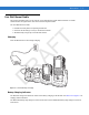
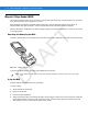
Accessories 7-5 Four Slot Ethernet Cradle This section describes how to set up and use a Four Slot Ethernet cradle with the MC75A. For cradle communication setup procedures refer to the MC75A Integrator Guide. The Four Slot Ethernet cradle: • Provides 5.4 VDC power for operating the MC75A. • Connects the MC75A (up to four) to an Ethernet network. Charging D R AF Insert the MC75A into a slot to begin charging. T • Simultaneously charges up to four MC75A devices.
7-6 MC75A Enterprise Digital Assistant User Guide Charging Temperature Charge batteries in temperatures from 0°C to 40°C (32°F to 104°F). Charging is intelligently controlled by the MC75A. D R AF T To accomplish this, for small periods of time, the MC75A or accessory alternately enables and disables battery charging to keep the battery at acceptable temperatures. The MC75A or accessory indicates when charging is disabled due to abnormal temperatures via its LED. See Table 1-2 on page 1-7.
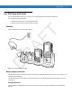
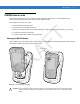
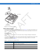
Accessories 7-7 Four Slot Charge Only Cradle This section describes how to set up and use a Four Slot Charge Only cradle with the MC75A. The Four Slot Charge Only cradle: • Provides 5.4 VDC power for operating the MC75A. • Simultaneously charges up to four MC75A devices. D R AF Insert the MC75A into a slot to begin charging. T Charging Figure 7-4 MC75A Battery Charging Battery Charging Indicators The MC75A’s charge LED shows the status of the battery charging in the MC75A.
7-8 MC75A Enterprise Digital Assistant User Guide D R AF T To accomplish this, for small periods of time, the MC75A or accessory alternately enables and disables battery charging to keep the battery at acceptable temperatures. The MC75A or accessory indicates when charging is disabled due to abnormal temperatures via its LED. See Table 1-2 on page 1-7.
Accessories 7-9 VCD7X00 Vehicle Cradle This section describes how to use a VCD7X00 vehicle cradle with the MC75A. For cradle installation and communication setup procedures refer to the MC75A Integrator Guide. Once installed in a vehicle, the cradle: • holds the MC75A securely in place • provides power for operating the MC75A • provides a serial port for data communication between an MC75A and an external device (e.g.
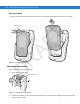
7 - 10 MC75A Enterprise Digital Assistant User Guide Removing the MC75A To remove the MC75A, hold back the release lever on the cradle and pull the MC75A up and out of the cradle. R AF T Release Lever Figure 7-6 Removing the MC75A D Charging the Spare Battery Insert a spare battery to begin charging: 1. Lift the battery release lever. Battery Release Lever Battery Figure 7-7 Inserting the Spare Battery 2.
Accessories 7 - 11 3. Release the battery release lever. The battery release lever locks the spare battery into place. To remove a spare battery, hold back the battery release lever and lift the battery from the spare battery slot. Battery Release Lever Figure 7-8 Removing the Spare Battery AF Battery Charging Indicators T Battery The Vehicle Cradle charges the MC75A’s main battery and a spare battery simultaneously. The MC75A’s charge LED indicates the status of the battery charging in the MC75A.
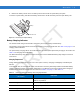
7 - 12 MC75A Enterprise Digital Assistant User Guide Four Slot Battery Charger This section describes how to use the Four Slot Battery Charger to charge up to four MC75A batteries. MC75A Battery Shim Installation AF T Before charging a spare battery, snap the MC75A shim into the battery slot as shown in Figure 7-9. R Shim Figure 7-9 MC75A Battery Shim Installation NOTE To purchase additional shims, contact your local account manager or Motorola, Inc. Part number: KT-76490-01R.
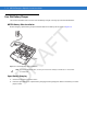
Accessories 7 - 13 Spare Battery Charging LEDs (4) AF T Spare Battery Figure 7-10 Four Slot Battery Charger R Battery Charging Indicators The charger has an amber LED for each battery charging well. See Table 7-4 for charging status indications. The 3600 mAh battery fully charges in less than five hours and the 4800 mAh battery fully charges in less than seven hours. D Charging Temperature Charge batteries in temperatures from 0°C to 40°C (32°F to 104°F).
7 - 14 MC75A Enterprise Digital Assistant User Guide Magnetic Stripe Reader (MSR) This section describes how to set up and use the snap-on MSR with the MC75A. The MSR snaps on to the bottom of the MC75A and removes easily when not in use. When attached to the MC75A, the MSR allows the MC75A to capture data from magnetic stripe cards. To download MSR data capture software, visit the Motorola web site at http://www.symbol.com/support.
Figure 7-12 Magnetic Stripe Card Swiping The application indicates if the data has been read correctly. D R AF 5.
7 - 16 MC75A Enterprise Digital Assistant User Guide Debit Card Reader The DCR7X00-100R Debit Card Reader (DCR) snaps onto the bottom of the MC70/MC75A mobile computer to allow easy data capture with the swipe of a magnetic stripe card and personal identification number (PIN) entry using a numeric keypad. This guide describes how to install and use the DCR. Getting Started When using the DCR for the first time, charge the DCR in a cradle for a minimum of three hours.
AF Figure 7-14 DCR Removal T Accessories 7 - 17 Credit Card Transactions Launch a transaction application on the MC75A. In the application, select Credit Card transaction. D R Swipe the credit card through the magnetic stripe reader (MSR) slot, orienting the magnetic stripe as shown. Data encoded on the credit card is captured and, depending on the application, may display in an application data field.
7 - 18 MC75A Enterprise Digital Assistant User Guide Figure 7-16 Swipe Card Swipe the card in either direction, from left to right, or right to left. For best results, gently press down on the card while swiping to ensure contact with the bottom of the slot. T NOTE R AF Turn the MC75A over and present the DCR keypad to the customer. The customer enters their PIN following the instructions on the DCR display.
Accessories 7 - 19 Table 7-5 Keypad Key Descriptions Key Description Used to enter PIN. Cancel Cancels the current transaction. Clear Clears the entered data. Enter Submits the entered data. Display Messages AF T Numeric The follow messages may appear on the DCR display: ENTER PIN - A PIN is required to complete the transaction. PIN ERR - The entered PIN is not between 4 and 12 characters. CANCELED - The transaction was cancelled by the user. COMPLETE - The transaction was completed.
7 - 20 MC75A Enterprise Digital Assistant User Guide • BATT LOW - Battery charge is low. If BATT LOW displays, charge the DCR for approximately three hours. D R AF Figure 7-19 Charging the DCR T To charge the DCR, place it in a cradle or connect it to a charging cable. The DCR also charges when connected to the MC75A and the transaction application is running.
Accessories 7 - 21 Snap-on Mobile Payment Module with Chip and PIN The DCR7X00-200R Snap-on Mobile Payment Module with Chip and PIN smart card reader snaps onto the bottom of the MC75A mobile computer to allow easy data capture with magnetic stripe cards, EMV compliant Chip and PIN cards and personal identification number (PIN) entry using a numeric keypad. This guide describes how to install and use the module.
7 - 22 MC75A Enterprise Digital Assistant User Guide Credit Card Transactions NOTE Credit Card transactions will function without an encryption key injected but will not function if a tamper event occurs. Launch a transaction application on the MC75A. In the application, select Credit Card transaction. NOTE AF Figure 7-22 Swipe Card T Swipe the credit card through the magnetic stripe reader (MSR) slot, orienting the magnetic stripe as shown.
Figure 7-24 Enter PIN Chip and PIN Transactions Chip and PIN transactions will function without an encryption key injected but will not function if a tamper event occurs. AF NOTE T Accessories 7 - 23 Launch a transaction application on the MC75A. In the application, select Chip and PIN transaction. D R Customer inserts the Chip and Pin card into the slot, orienting the card with the contacts facing down and toward the DCR keypad.
7 - 24 MC75A Enterprise Digital Assistant User Guide Table 7-6 Keypad Button Descriptions Key Description Clear (Yellow) Cancels the current transaction. Clears the entered data. Submits the entered data. R Enter (Green) Used to enter PIN. AF Numeric Cancel (Red) T Figure 7-26 Keypad Display Messages After connecting the module to the MC70/MC75 and an application opens the COM port, the following displays: D .
Accessories 7 - 25 Table 7-7 Keyload Codes Display Operating Status M M - M M - M M - M M - Normal d d d - m m - m m - m m m m Return to key injection facility. T D D D - AF Return to Motorola for service. * * * * * Blank display The follow messages may appear on the display: Table 7-8 Display Messages Message Line 1: Line 2: Enter PIN Instructs the user to enter their PIN. Displays “*” as PIN is entered and instructs the user to press enter key when done.
7 - 26 MC75A Enterprise Digital Assistant User Guide Headset Use the headset to communicate via Voice-Over-IP (VOIP) or for audio playback and telephony applications. To connect the headset, remove the plug from the headset jack at the top of the MC75A and insert the headset connector. Contact a Motorola representative for compatible headsets. AF T For best performance, Motorola recommends a 2.5mm jack headset, p/n 50-11300-050R.
Accessories 7 - 27 Cables This section describes how to set up and use the cables. The cables are available with a variety of connection capabilities. The following communication/charge cables are available: • Serial (RS232) Charge cable (9-pin D female with power input receptacle) • USB Client Charge cable (standard-A connector and a barrel receptacle for power) • Auto charge cable • Modem inverter cable • Charge only cable.
7 - 28 MC75A Enterprise Digital Assistant User Guide 2. Slide the bottom of the MC75A into the connector end of the communication/charge cable and gently press in until it latches into the MC75A. The MC75A amber Charge LED indicates the MC75A battery charging status. The 3600 mAh standard battery charges in less than five hours and the 4800 mAh standard battery charges in less than seven hours. See Table 1-2 on page 1-7 for charging status indications. 3.
AF Introduction T Chapter 8 Maintenance & Troubleshooting This chapter includes instructions on cleaning and storing the MC75A, and provides troubleshooting solutions for potential problems during MC75A operation. Maintaining the MC75A For trouble-free service, observe the following tips when using the MC75A: R • Do not scratch the screen of the MC75A. When working with the MC75A, use the supplied stylus or plastic-tipped pens intended for use with a touch-sensitive screen.
8-2 MC75A Enterprise Digital Assistant User Guide Removing the Screen Protector A screen protector is applied to the MC75A. Motorola recommends using this to minimize wear and tear. Screen protectors enhance the usability and durability of touch screen displays. To remove the screen protector, lift the corner using a thin plastic card, such as a credit card, then carefully lift it off the display.
Maintenance & Troubleshooting 8-3 • Severe impact from dropping any battery-operated device on a hard surface could cause the battery to overheat. • Do not short circuit a battery or allow metallic or conductive objects to contact the battery terminals. • Do not modify or remanufacture, attempt to insert foreign objects into the battery, immerse or expose to water or other liquids, or expose to fire, explosion, or other hazard.
8-4 MC75A Enterprise Digital Assistant User Guide Display The display can be wiped down with the alcohol wipes, but care should be taken not to allow any pooling of liquid around the edges of the display. Immediately dried the display with a soft, non-abrasive cloth to prevent streaking. Scanner Exit Window Wipe the scanner exit window periodically with a lens tissue or other material suitable for cleaning optical material such as eyeglasses. Connector Remove the main battery from mobile computer.
Maintenance & Troubleshooting 8. 8-5 Allow at least 10 to 30 minutes (depending on ambient temperature and humidity) for the alcohol to air dry before applying power to cradle. If the temperature is low and humidity is high, longer drying time is required. Warm temperature and dry humidity requires less drying time. Cleaning Frequency The cleaning frequency is up to the customer’s discretion due to the varied environments in which the mobile devices are used.
8-6 MC75A Enterprise Digital Assistant User Guide Table 8-1 Troubleshooting the MC75A (Continued) Cause During data communication, no data transmitted, or transmitted data was incomplete. Replace the MC75A in the cradle, or reattach the communication cable and re-transmit. Incorrect cable configuration. See the system administrator. Communication software was incorrectly installed or configured. Perform setup. Refer to the MC75A Enterprise Digital Assistant Integrator Guide for details.
Maintenance & Troubleshooting 8-7 Table 8-1 Troubleshooting the MC75A (Continued) Problem Cause Solution The MC75A’s battery is low. Recharge or replace the battery. The internal Bluetooth radio is powered on for a long time. Because this mode requires battery power, power it off when not needed. The MC75A does not accept data capture input. Scanning application is not loaded. Load a scanning application on the MC75A. See the system administrator. Unreadable bar code.
8-8 MC75A Enterprise Digital Assistant User Guide Table 8-2 Troubleshooting Bluetooth Connection (Continued) Solution When trying to connect a Bluetooth phone and MC75A, the phone thinks a previously paired MC75A is used. The phone remembers the name and address of the MC75A it last paired with via the Bluetooth radio. Manually delete the pairing device and name from the phone. Refer to the phone’s user documentation for instructions.
Maintenance & Troubleshooting 8-9 Table 8-3 Troubleshooting the Single Slot USB/Serial Cradle (Continued) MC75A was removed from cradle or cradle was unplugged from AC power too soon. Ensure cradle is receiving power. Ensure MC75A is seated correctly. Confirm main battery is charging under Start > Settings > Power. Battery is faulty. Verify that other batteries charge properly. If so, replace the faulty battery. The MC75A is not fully seated in the cradle.
8 - 10 MC75A Enterprise Digital Assistant User Guide Four Slot Ethernet Cradle Table 8-4 Troubleshooting the Four Slot Ethernet Cradle Symptom Cause Solution MC75A was removed from cradle during communications. Replace MC75A in cradle and retransmit. MC75A has no active connection. An icon is visible in the status bar if a connection is currently active. Battery is not charging. MC75A removed from the cradle too soon. Replace the MC75A in the cradle.
Maintenance & Troubleshooting 8 - 11 Table 8-5 Troubleshooting the Vehicle Cradle Possible Cause No data transmitted, or transmitted data was incomplete. Action MC75A removed from cradle during communication. Replace MC75A in cradle and retransmit. No null modem cable was used. Some external devices require a null modem cable. Retransmit using a null modem cable. Incorrect cable configuration. See the system administrator. Cable missing or disconnected. Re-connect cable.
8 - 12 MC75A Enterprise Digital Assistant User Guide Cables Table 8-7 Troubleshooting the Cables During data communication, no data transmits, or transmitted data was incomplete. Action MC75A was disconnected from AC power too soon. Connect the power cable correctly. Confirm main battery is charging under Start > Settings > Power. Battery is faulty. Verify that other batteries charge properly. If so, replace the faulty battery. The MC75A is not fully attached to power.
Maintenance & Troubleshooting 8 - 13 Table 8-8 Troubleshooting the Magnetic Stripe Reader (Continued) MC75A was removed from MSR or MSR was unplugged from AC power too soon. Ensure MSR is receiving power. Ensure MC75A is attached correctly. Confirm main battery is charging under Start > Settings > Power. Battery is faulty. Verify that other batteries charge properly. If so, replace the faulty battery. The MC75A is not fully attached to the MSR.
D R AF T 8 - 14 MC75A Enterprise Digital Assistant User Guide
AF MC75A Technical Specifications T Appendix A Technical Specifications The following tables summarize the MC75A’s intended operating environment and technical hardware specifications. MC75A Table A-1 MC75A Technical Specifications Description R Item Physical Characteristics D Dimensions MC75A0: Length: 15.2 cm (6.00 in.) Width: 8.4 cm (3.30 in.) Depth: 4.4 cm (1.70 in.) MC75A6/8: Length: 17.9 cm (7.05 in.) Width: 8.4 cm (3.30 in.) Depth: 4.4 cm (1.70 in.) Weight MC75A0: 364 g (12.
A-2 MC75A Enterprise Digital Assistant User Guide Table A-1 MC75A Technical Specifications (Continued) Item Description LED backlight Main Battery Rechargeable Lithium Ion 3.7V, 1950, 3800 or 4800 mAh Smart Battery Backup Battery NiMH battery (rechargeable) 15 mAh 2.4V (not user-accessible) Expansion Slot User accessible microSD slot (with secure cover).