
User Manual


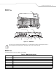

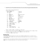

Table Of Contents
- About This Guide
- Introduction
- Getting Started
- Installation and Communication
- Administrator Console
- Maintenance and Troubleshooting
- Specifications

Installation and Communication 2-3
XR400 Parts
Figure 2-1. XR400 Parts
Use only the parts provided with the XR400 reader or recommended by Symbol. Substituting other cables or
parts can degrade system performance, damage the reader, and/or void the warranty.
XR400 Ports
The following table lists the ports available on the XR400.
Table 2-1. XR400 Port Descriptions
Port Description
Antenna/Read Points Connect up to eight antennas (four transmit, four receive)
10/100BaseT Ethernet Insert an RJ45 Ethernet cable for connection to an Ethernet network or an Ethernet card on a host PC.
USB Client Insert a USB cable for USB client connection to a host device.
USB Host Insert a USB cable for USB host connection to a client device.
GPIO Insert a DB15 serial cable for connection to the DC200 Portal. The XR400 controls the DC200 LEDs and motion sensor.
RS232 Insert a DB9 serial cable for RS232 connection to a host PC.
Power Connect a 24 V 1.2 A power supply. The power supply’s DC connector connects to an AC adapter that varies depending on the country.
Antenna/Read Points
USB Client
10/100BaseT Ethernet
GPIO
RS232
Power
LEDs
USB Host
CAUTION