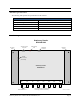
Stationary Reader (Part# RDR-MP-001) User’s Manual Published: January 30, 2002 Document Control Number: MNI01H001 Matrics, Inc. 8850 Stanford Boulevard Suite 3000 Columbia, MD 21045 Tel: 410.872.0300 Fax: 410.872.0700 http://www.matricsrfid.
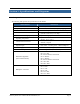
Contents SECTION 1. INTRODUCTION ..................................................................................................3 Document Conventions ....................................................................................................3 Acronyms and Abbreviations ...........................................................................................3 Disclaimer........................................................................................................................
Section 1. Introduction This User’s Manual, designed for the Matrics, Inc. RFID system user, describes the Stationary Reader (Part# RDR-MP-001) and how to install it. Document Conventions The following conventions are used in this User’s Manual: CONVENTION Hyperlink 1. Numbered list • Bulleted list DESCRIPTION Click marked text to immediately move to information (or web site). Example: http://www.matricsrfid.
Section 2. System Description Matrics develops and markets Radio Frequency Identification (RFID) that is effective and affordable by offering a combination of low cost, long read range, and a very high read rate unmatched by other RFID systems. A typical Matrics RFID system consists of three components: • • • Silicon-based RFID tags, Reader network components (readers, antennas, cables, power supplies, CAT3 cable termination blocks, etc.
Section 3. Specifications and Diagrams Reader Specification The following table provides the specifications for the Reader: CHARACTERISTIC Name/Part Number Operating Frequency System Architecture Dimensions Simultaneous Reading Capability Operating Temperature Communications Interface Inputs/Outputs Power Supply Power Consumption RJ45 Pin Assignments (host communications) Multiplexer connection Stationary Reader User’s Manual 2001-2002 Matrics, Inc.
Antenna Specification The following table provides the specifications for the antenna: CHARACTERISTIC AT Name/Part Number Input Standing Wave Ratio (VSWR) Isolation -db 3db Beam Width Gain in dbd/linear 915 MH Z General Purpose Antenna, RAN-GP-001 1.25 -37 60° 6 Reader Diagram Stationary Reader RDR-MP-001 Mounting Plate 485 / Bus Power Connector Power/Activity LED Multiplexer Connector Mounting Plate +24VDC 1.
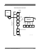
Connections Diagram Functional System Connections Std 485 Bus Terminator R x ± ] 120Ω Tx ± ] 120Ω Host/PC Bus Power Wiring Block RJ45 5' Patch Wiring Block unspec. 485 convertor Belden #88757 or equivalent (22 ga. CAT3) RJ45 250' max. bus powered -or500' max. locally powered Wiring Block Local Power (optional) Stationary Reader RDR-MP-001 CAT5 std patch 5' max. 1 3 2 4 Reader 1 mini UHF Wiring Block General Purpose Antenna Wiring Block RG-142B (25' max.
Section 4. Installation Check that you have everything you need before you proceed with the installation. In addition to this User’s Manual, you should have received the following items in your package: • • • • • • One Matrics Stationary Reader (Part# RDR-MP-001) Wall mount Power Supply (optional) Mounting equipment CAT5 jumper cable CAT3 cable termination block (“wiring block”) Utility software.
Installation Procedure The Reader installation consists of the following steps: 1. Mount your antenna(s) in a location chosen for optimum operation. Make sure that you follow the FCC guidelines for antenna placement. The antenna should be at least two (2) meters from any unsuspecting personnel. 2. Mount the Reader on a wall near your antenna(s) locations. CAUTION: The Reader must reside indoors, in operating range, and out of direct sunlight, high moisture, or extreme temperatures. 3.
Section 5. Cautions, Notes, and Approvals Matrics products are approved (or approval pending) by the appropriate regulatory agencies: • • Federal Communications Commission (FCC), Part 15 Underwriter Laboratory, UL 294 Note: This equipment has been tested and found to comply with the limits for a Class A digital device, pursuant to Part 15 of the FCC Rules. These limits are designed to provide reasonable protection against harmful interference when the equipment is operated in a commercial environment.
Section 6. Limited Warranty Matrics warrants its products to the original purchaser to be free of defects in workmanship and material for a period of ninety (90) days from date of receipt. Matrics’ sole and complete responsibility under this warranty is expressly limited to repair or replacement of the defective product. Replacement products may be new or reconditioned.
Section 7. Troubleshooting In the event you encounter a problem with your Reader, refer to the following table for possible solutions: PROBLEM POSSIBLE CAUSE SOLUTION The Power/Activity LED doesn’t light. The AC outlet may not be working or may be controlled by a wall switch. Plug a different electrical appliance into the outlet and turn it on. If the appliance doesn’t work, plug the Reader into a different outlet. The Power/Activity LED is on but doesn’t blink.
Section 8. Contact Us For general and technical assistance, contact Matrics at: Tel: 410.872.0300 Monday-Friday 8:30 a.m. – 5:00 p.m. EST Fax: 410.872.0700 http://www.matricsrfid.com/ Matrics, Inc. 8850 Stanford Boulevard Suite 3000 Columbia, MD 21045 USA Stationary Reader User’s Manual 2001-2002 Matrics, Inc.