P D T 7 5 0 0 S e r i e s
P D T 7 5 0 0 S e r i e s 1999-2000 SYMBOL TECHNOLOGIES, INC. All rights reserved. Symbol reserves the right to make changes to any product to improve reliability, function, or design. Symbol does not assume any product liability arising out of, or in connection with, the application or use of any product, circuit, or application described herein.
Q u i c k R e f e r e n c e Introduction The PDT 7500 Series portable data terminal puts the processing power of a 486 PC in the user’s hand. The terminal uses a rechargeable Lithium-Ion 1400 mAh smart battery, and incorporates pen technology and bar code scanning capability in a key-based terminal. The PDT 7500 ruggedized hand-held terminal combines: • • • • • • • • PC-standard architecture (32-bit 486 DX2) Microsoft® MS-DOS 6.
P D T 7 5 0 0 S e r i e s About This Guide This guide provides information on the operation of the PDT 7500 Series terminal.
Q u i c k R e f e r e n c e Parts of the PDT 7500 Front View WAN Antenna (PDT 753X only) Scan LED LCD Scan Button Communication LED Battery Charge LED Thumb Rest Power Key Top View Scan Window 3
P D T 7 5 0 0 S e r i e s Parts of the PDT 7500 (continued) Bottom View Serial Communications Port IrDA Port Back View Li-Ion Battery Battery Latch 4
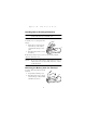
Q u i c k R e f e r e n c e Installing New or Recharged Batteries Caution: To ensure proper terminal operation, use ONLY the Symbol Li-Ion battery in the PDT 7500. To install a new or recharged Li-Ion battery: 1. Hook the base of the new battery in the top of the battery compartment, then press into place. 2. Slide the battery latch to secure the battery. If the battery latch is not closed, do not operate the terminal, otherwise data may be lost.
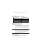
P D T 7 5 0 0 S e r i e s 3. Lift the battery up and out of the battery compartment. Charging the Battery in the Terminal To charge the terminal’s battery, place the PDT 7500 in the cradle or connect the synchronization/charging cable. The terminal’s charging LED turns yellow while charging, then turns green when the battery is fully charged, which takes 2-3 hours. A flashing yellow LED indicates there may be a problem with the battery.
Q u i c k R e f e r e n c e LED Indication For all charging methods, the terminal’s battery charging LED indicates the battery charging status as follows: Battery Charge State Charge LED Indication Battery absent/no charge power Off Battery charging Yellow Battery fully charged Green Abnormal battery Flashing Yellow Operating the PDT 7500 Powering the Terminal On/Off Note: Before the terminal can be powered on, it must be initialized and the battery must be fully charged.
P D T 7 5 0 0 S e r i e s Controlling the Screen Contrast To lighten the screen contrast, press the blue FUNC key, then the LIGHT key. To darken the screen contrast, press the FUNC key, then the DARK Key. Resetting the PDT 7500 If your PDT 7500 Series terminal stops responding to input from buttons on the screen, you must reset it. Performing a Warm Boot (DOS and Windows CE Terminals) A warm boot restarts the terminal and saves all stored records and entries.
Q u i c k R e f e r e n c e To perform a hard reset: 1. Remove the battery for 20 minutes or longer. 2. Replace the battery in the terminal. 3. The calibration screen displays. Note: With a hard reset, formats preferences and other settings are restored to their original factory defaults. Calibrating the Screen (Windows CE Terminals Only) The first time you start your PDT 7500 terminal (and whenever the terminal is cold-booted), the calibration screen displays.
P D T 7 5 0 0 S e r i e s Using the PDT 7500 36-Key Keypad The 36-key keypad uses an alphanumeric keypad that produces the 26-character alphabet (A-Z), numbers (0-9), and assorted characters. The keypad is color-coded to indicate which modifier key (ALPHA, CTRL, FUNC, and SHIFT) to press to produce a particular character or action. Alpha key Scan button ALPHA Shift key FUNC CLEAR SHIFT ENTER CTRL Control key Enter key 7 8 9 4 5 6 1 2 3 , 0 .
Q u i c k R e f e r e n c e • • Press ENTER after entering data or a command. Press CTRL to perform the control function. This key is under application control. • Press SHIFT and a key to produce various character keys; refer to the PDT 7500 Series Product Reference Guide for your terminal or your application guide for the keypad mapping. Note: Key functions can be changed by an application. Your keypad may not function exactly as described above.
P D T 7 5 0 0 • S e r i e s Press the cursor keys ( , , , ) to move the cursor left, right, up and down on the screen. • Press BKSP to erase information entered on the display, one character at a time. • Press SPACE (in the FUNC state) to enter a blank space. • Press CLEAR to partially or completely escape from an application level or screen. CLEAR also erases all entered data from the screen. • Press ENTER after entering data or a command. • Press CTRL to perform the control function.
Q u i c k R e f e r e n c e Using the PDT 7500 25-Key Keypad The 25-key keypad produces the numbers 0-9, function keys F1F10 and various action keys. Scan button EN TE ENT R Enter key SEND Send key Backspace key ER Function key FUNC 7 8 9 4 5 6 1 2 3 , 0 . BACK _ CLEAR • • Clear key Power key The default numeric keypad produces the numbers 0-9. Press FUNC and the corresponding numeric key to produce the function keys F1-F10.
P D T 7 5 0 0 S e r i e s Using the Integrated Laser Scanner To use the laser scanner: 1. Verify the system is on. The LED lights yellow if scanning is enabled and the laser is on. 2. Aim the PDT 7500 scan window at the bar code and press the scan button. Do not hold the PDT 7500 at a right angle to the bar code. You can tilt the 7500 up to 65° forward or backward and achieve a successful decodes. 3. Ensure that the scan beam crosses all bars and spaces on the symbol, as shown below.
Q u i c k R e f e r e n c e 1. Point the scanner at the bar code and press the scan button. Slab Raster 2. As the raster pattern spreads, keep the pattern in the same horizontal plane as the bar code. 3/4” 3/4” 3. The terminal indicates a successful scan by changing the LED from yellow to green, beeping one or more times, and/or displaying the decoded bar code on the screen. “Tall” PDF Bar Codes If the PDF417 symbol is “tall,” the vertical scan pattern may not be high enough to cover it.
P D T 7 5 0 0 S e r i e s The scan beam does not have to be perfectly parallel with the top and bottom of the symbol (up to a 4o tilt will work). Using the Imager To scan a symbol: 1. Press the scan button and center the symbol in any orientation in the aiming pattern. The entire symbol must be within the brackets. Linear bar code PDF417 symbol Symbol Aiming Pattern 2. Hold down the scan button until the imager beeps, indicating the bar code is decoded.
Q u i c k R e f e r e n c e Host Communications The PDT 7500 Series terminal can communicate with a host PC either directly through its communications port using an RS-232 serial cable or the cradle, or wirelessly via the Spectrum24® wireless LANs. For more information on setting up and performing wireless communications with your PDT 7540 Series terminal, refer to the PDT 7500 Series Product Reference Guide. Using the RS-232 Serial Cable To connect the RS-232 serial cable for host communication: 1.
P D T 7 5 0 0 S e r i e s run the application’s print function. Printer communication can also be established through an RS-232 cable connected directly to the printer. Using the Touch Screen Some PDT 7500 terminals are equipped with a Touch Screen, which has software that allows the stylus to function as a mouse. An optional stylus is available from Symbol for use with the terminal. Further use of the stylus function is application-dependent. Refer to application documentation for more information.
Q u i c k Problem R e f e r e n c e Cause Solution Scanner does not power on when the scan button is pressed. Scanner is not enabled. See your System Administrator. Scanner does not decode a bar code. Bar code is unreadable. Verify that the bar code is not defective, i.e., smudged or broken. Scan window is dirty. Clean scan window with a lens tissue. Tissues for eyeglasses work well. Do not use tissues coated with lotion. Scan code not enabled. See your System Administrator.
P D T Problem The aiming pattern does not appear when the scan button is pressed. The Imager is having trouble reading symbols. Scanned data is displayed incorrectly or not at all. 7 5 0 0 Cause S e r i e s Solution Bad cable connection. Check that the cable is connected properly. Host power not on. Be sure the host system power is on (if external power isn’t used). Laser aiming parameter not enabled. Ensure the laser aiming parameter is enabled. Symbology disabled.
Q u i c k R e f e r e n c e Serial Communication Port Pin-Outs Pin Description 1 GND 2 DSR 3 RXD 4 CTS 5 DCD 6 GND 7 PWROUT (+5V) 8 PWRIN(+15V) 9 DTR 10 Ring 11 TXD 12 RTS 13 Reserved 14 GND 15 PWRIN(+15V) Ergonomic Recommendations Caution: In order to avoid or minimize the potential risk of ergonomic injury follow the recommendations below.
P D T 7 5 0 0 S e r i e s Regulatory Information Radio Frequency Interference Requirements This device has been tested and found to comply with the limits for a Class A digital device pursuant to Part 15 of the Federal Communications Commissions Rules and Regulation. These limits are designed to provide reasonable protection against harmful interference when the equipment is operated in a commercial environment.
Q u i c k R e f e r e n c e CE Marking and European Union Compliance Products intended for sale within the European Union are marked with the CE Mark which indicates compliance to applicable Directives and European Normes (EN), as follows.
P D T 7 5 0 0 S e r i e s RF Devices Symbol’s RF products are designed to be compliant with the rules and regulations in the locations into which they are sold and will be labeled as required. The majority of Symbol’s RF devices are type approved and do not require the user to obtain license or authorization before using the equipment. Any changes or modifications to Symbol Technologies equipment not expressly approved by Symbol Technologies could void the user’s authority to operate the equipment.
Q u i c k R e f e r e n c e Scanner Labeling AVOID EXPOSURE - LASER LIGHT IS EMITTED FROM THIS APERTURE ÉVITER TOUTE EXPOSITION LUMIÈRE LASER ÉMIS PAR CETTE OUVERTURE This label is located inside the battery compartment.
P D T 7 5 0 0 S e r i e s In accordance with Clause 5, IEC 0825 and EN60825, the following information is provided to the user: ENGLISH CLASS 1 CLASS 2 DANISH KLASSE 1 KLASSE 2 DUTCH KLASSE 1 KLASSE 2 FINNISH LUOKKA 1 LUOKKA 2 FRENCH CLASSE 1 CLASSE 2 GERMAN KLASSE 1 KLASSE 2 HEBREW CLASS 1 LASER PRODUCT LASER LIGHT DO NOT STARE INTO BEAM CLASS 2 LASER PRODUCT KLASSE 1 LASERPRODUKT LASERLYF SE IKKE IND I STRÅLEN KLASSE 2 LASERPRODUKT AL LASER DI CLASSE 2 ITALIAN CLASSE 1 CLASSE 2 KLASSE-1 LASERP
Q u i c k R e f e r e n c e DECLARATION OF CONFORMITY We, Symbol Technologies, Inc. of One Symbol Plaza, Holtsville, NY 11742-1300, USA declare under our sole responsibility that the product Spectrum24, LA3021, Type II Radio Card Spectrum24, LA302C, Type II Radio Card Spectrum24, LA302T, Type II Radio Card to which this declaration relates, is in conformity with the following standards and/or other normative documents.
P D T 7 5 0 0 S e r i e s DECLARATION OF CONFORMITY We, Symbol Technologies, Inc. of One Symbol Plaza, Holtsville, NY 11742-1300, USA declare under our sole responsibility that the product Spectrum24HR, LA4111, Type II Radio Card Spectrum24HR, LA411T, Type II Radio Card to which this declaration relates, is in conformity with the following standards and/or other normative documents.
Q u i c k Note: R e f e r e n c e The following End-User License Agreement applies only to Windows CE versions of the PDT 7500 terminal. END-USER LICENSE AGREEMENT FOR MICROSOFT SOFTWARE MICROSOFT EXPORT SOFTWARE DEVELOPMENT KIT FOR WINDOWS CE VERSION 2.
P D T 2. 3. 7 5 0 0 S e r i e s Platform Developer), (“Sample Code”) to develop, and test your Application for Windows CE. You may also reproduce and distribute the Sample Code in object code form, along with any modifications you make to the Sample Code, provided that you comply with the Distribution Requirements described below. For purposes of this section, “modifications” shall mean enhancements to the functionality of the Sample Code. c. Distribution Requirements.
Q u i c k R e f e r e n c e d. 4. 5. Software Transfer. You may not transfer any of your rights under this EULA e. Termination. Without prejudice to any other rights, Microsoft may terminate this EULA if you fail to comply with the terms and conditions of this EULA. In such event, you must destroy all copies of the SOFTWARE PRODUCT and all of its component parts. EXPORT RESTRICTIONS.
P D T 7 5 0 0 S e r i e s NO LIABILITY FOR DAMAGES. In no event shall Microsoft or its suppliers be liable for any damages whatsoever (including, without limitation, damages for loss of business profits, business interruption, loss of business information, or any other pecuniary loss) arising out of the use of or inability to use this Microsoft product, even if Microsoft has been advised of the possibility of such damages.
Q u i c k R e f e r e n c e Warranty Symbol Technologies, Inc. (“Symbol”) manufactures its hardware products in accordance with industry-standard practices. Symbol warrants that for a period of twelve (12) months from date of shipment, products will be free from defects in materials and workmanship. This warranty is provided to the original owner only and is not transferable to any third party.
Service Information Before you use the unit, it must be configured to operate in your facility’s network and run your applications. If you have a problem running your unit or using your equipment, contact your facility’s Technical or Systems Support.