VC5090 Vehicle Computer Quick Reference Guide PRELIMINARY
VC5090 Vehicle Computer © 2006 SYMBOL TECHNOLOGIES, INC. All rights reserved. Symbol reserves the right to make changes to any product to improve reliability, function, or design. Symbol does not assume any product liability arising out of, or in connection with, the application or use of any product, circuit, or application described herein.
Quick Reference Guide 3 Introduction The VC5090 Vehicle Computer is a vehicle or fixed-mount computer. The VC5090 has two configurations: a full-screen computer with optional keyboard and a half screen configuration with a built in keyboard. You can enter data using the touch screen, the keyboard, an optional bar code scanner, or a combination of the three. The data is transmitted wireless to a host computer.
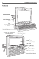
VC5090 Vehicle Computer Features Mounting Bracket Angle Adjustment Knob User Programmable Buttons Optional Keyboard Antenna Port for Optional External Antenna Main Power Switch Display WLAN COMM LED Power LED Power Button Control Button Control LED Built-In Keyboard
Quick Reference Guide 5 UPS/Storage Card Door Desiccant Door USB Ports Client or Host) Power Connector COM2 Port Connector Audio COM1 Port Connector Connector USB Keyboard Connector Unpacking You should find the following items in the box: • • • • • • • • VC5090 vehicle computer mounting bracket hardware bag desiccant kit three fuses and three fuse holders power cable non-abrasive screen protector four 3/8 x 6 x 2” cap screws, eight flat washers, eight lock washers and four hex nuts • this guide.
• • • • • VC5090 Vehicle Computer Printer cables RS-232 and USB ActiveSync cables AC power supply Uninterruptable power supply (UPS) Replacement desiccant bag kit. Refer to the VC5090 Product Reference Guide for information on installation the vehicle computer in a vehicle or mounted on a wall. Mounting Bracket Installation NOTE The vehicle computer and bracket must be firmly secured to a surface that can support the vehicle computer’s weight.
Quick Reference Guide 7 Installing the Desiccant Bags 1. Remove the tape securing the desiccant door to the back housing. 2. Open the desiccant package and remove the six desiccant bags. 3. Place three desiccant bags in the desiccant well. 4. Place the other three desiccant bags in the back of the desiccant door. 5. Carefully place the desiccant door onto the back housing. Ensure that the desiccant packets do not interfere with placement of the door. 6.
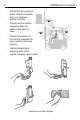
VC5090 Vehicle Computer - Check that the positions of the vehicle computer does not obstruct vehicle controls. - Check that the vehicle computer does not obstruct the driver's view. - Check the position of the vehicle computer for user comfort over long periods. - Check positioning to avoid extreme wrist angles that may cause injury.
Quick Reference Guide 9 Optimum Wrist Position Mounting the Vehicle Computer Important Fixing Information Any modification to supplied mounting bracket could cause early failure of the unit/mountings. • A minimum of four fixing positions must be used. • All nuts and bolts must be checked periodically and tightened if required. • When installing the vehicle computer, care must be taken to ensure that the mounting bracket footprint is fully supported. Additional plates may be required to achieve this.
VC5090 Vehicle Computer Washers Nuts Vehicle Cross-Beam Mounting Bracket Bolts Mounting onto an Over-Head Cage The diagram below illustrates a typical installation where the vehicle computer is mounted on a cage.
Quick Reference Guide 11 Mounting on a Dashboard or Horizontal Surface The diagram below illustrates a typical installation where the vehicle computer is mounted on a dashboard or hortizontal flat surface. Bolts Mounting Bracket Washers Mounting Surface Nuts Routing Electrical Cables • Establish a neat route for the cable, staying clear of moving parts or hot surfaces wherever possible.
VC5090 Vehicle Computer • On gasoline, diesel or propane vehicles, take the power from as close to the battery terminals as possible, and avoid using existing wiring. • All fuses must be as close as possible to the power source. • If you are unsure of the correct power source, contact the vehicle manufacturer for more information. 12-24V Gasoline, Diesel, or Propane Forklifts WARNING! A lead acid battery can leak hydrogen gas. A spark anywhere near the battery can cause it to explode.
Quick Reference Guide 13 Ignition Switch FUSE - 1A Yellow Vehicle Battery Power Cable 25-71919-01 Red FUSE - 20A VC5090 Black FUSE - 20A Green Chassis ground 1. Connect the green wire to the vehicle's chassis. If you cannot find a close connection point, solder an extra length of cable to the green wire to extend the connection to the chassis. Use a heat shrink to cover the solder joint. 2. Crimp a ring terminal onto the green wire and screw the ring terminal into the vehicle metal work.
5. VC5090 Vehicle Computer Connect the red wire to the vehicle's positive power source. Connect the black wire to the vehicle's negative power source. To terminate the cable: • If the vehicle has a power output connector, use a mating connector. You may be able to connect to a fuse panel with a commercially available connector. • If the vehicle has no power output connector, use a ring terminal (for a battery post) or blade terminal (for a fuse panel). 6.
Quick Reference Guide 15 CAUTION Use extreme care when routing and securing this cable from the vehicle computer to the vehicle power source. Hazards associated with improper wiring can be severe. To avoid unintentional contact between the wire and any sharp edges, use proper bushings and clamping where the cable passes through openings. If the wire is subjected to sharp surfaces and excess engine vibration, the wiring harness insulation can wear away, causing a short between the bare wire and chassis.
VC5090 Vehicle Computer 1. Connect the green wire to the vehicle’s chassis. If you cannot find a close connection point, solder an extra length of cable to the green wire to extend the connection to the chassis. Use a heat shrink to cover the solder joint. 2. Crimp a ring terminal onto the green wire and screw the ring terminal into the vehicle metal work.
Quick Reference Guide 17 4. Ensure the wiring connections created are sufficiently insulated from each other. 5. Re-connect the vehicle battery. 6. Insert the power cable connector into the vehicle computer's Power port. Align the keyway on the power connector with the notch on the vehicle computer’s power port. Installing the VC5090 on a Wall or Desktop To use the vehicle computer in a wall or desktop mounted application: 1.
VC5090 Vehicle Computer AC Line Cord Universal Power Supply (50-14001-004) DC Power Cable (25-71920-01) Power Port 1. Plug the other end of the AC power cable into a wall outlet. Installing the Optional Keyboard NOTE The optional keyboard is only available for the full-screen configuration. The keyboard kit contains the following items: • keyboard • keyboard brackets (2) • four M4 screws and washers • two locking knobs. 1.
Quick Reference Guide 19 Left Hand Bracket M4 Screws & Washers Locking Knob • Torque the screws to 230 kgf/cm. 1. Squeeze the levers on the keyboard and align the keyboard with the brackets. 2. Release the levers to insert the mechanism bars through an adjustment hole on each of the brackets. 3. Insert the keyboard locking knobs through the brackets and screw into the keyboard. 4. Plug the keyboard cable into the USB/Keyboard connector.
VC5090 Vehicle Computer Powering the VC5090 On/Off The Main Power switch provides power to the VC5090. You should only use this switch when removing power completely from the device. Main Power Switch Use the Power button on the front panel to place the VC5090 into Suspend mode or wake the VC5090 from Suspend mode. Power Button Charging the Internal Backup Battery When you receive your VC5090, leave the VC5090 powered on for 24 hours to fully charge the internal backup battery.
Quick Reference Guide 21 Controlling Screen Brightness There are four levels of screen brightness. To adjust the brightness of the screen, press the Control button on the front panel. The amber Control LED lights indicating that the VC5090 is in the control mode. Press the P1 button to decrease the brightness or the P2 button to increase the brightness. Press the Control button to exit this mode.
VC5090 Vehicle Computer Performing a Cold Boot A cold boot restarts the vehicle computer, but erases all stored records and entries in RAM. Data saved in flash memory or a memory card is not lost. In addition it returns formats, preferences and other settings to the factory default settings. There are two ways to perform a cold boot: • Simultaneously press and hold the Power, P1 and P3 buttons.
Quick Reference Guide 23 Maintenance The vehicle computer is factory-sealed (except for the desiccant door and UPS/SD Card door) and contains no user-serviceable parts. Only qualified Symbol Service Centers should service the vehicle computer. Use the protective caps that came with the vehicle computer to protect unused connectors. • Clean the casing, keyboard, and display window by wiping with a soft cloth. Use a damp cloth if necessary. • Never use solvents or abrasive cleaners.
VC5090 Vehicle Computer Troubleshooting Problem Cause VC5090 does not power on or shuts off suddenly. Power switch on top of vehicle computer is in the Off position. Power cable not connected or unplugged. Cannot see characters on display. Application does not respond. Optional scanner does not operate. Solution Turn the power switch to the On position. Connect power cable to power cable port on underside of vehicle computer. Press the Power button to boot up the VC5090.
Quick Reference Guide 25 Regulatory Information All Symbol devices are designed to be compliant with rules and regulations in locations they are sold and will be labeled as required. Regulatory Information is available in French, Italian, German, Spanish (Spain), Portuguese, Japanese, Korean, Russian, Simplified Chinese and Traditional Chinese. Please see following website: http://www.symbol.com/services/manuals/ and look for your specific product.
VC5090 Vehicle Computer Please refer to the Symbol Declaration of Conformity (DoC) for details of other country markings. This is available at http://www2.symbol.com/doc/. Note 1: For 2.
Quick Reference Guide 27 Vehicle Installation RF signals may affect improperly installed or inadequately shielded electronic systems in motor vehicles (including safety systems). Check with the manufacturer or its representative regarding your vehicle. You should also consult the manufacturer of any equipment that has been added to your vehicle. An air bag inflates with great force.
VC5090 Vehicle Computer Other Medical Devices Please consult your physician or the manufacturer of the medical device, to determine if the operation of your wireless product may interfere with the medical device. FCC / EU RF Exposure Guidelines Safety Information The device complies with Internationally recognized standards covering Specific Absorption Rate (SAR) related to human exposure to electromagnetic fields from radio devices.
Quick Reference Guide 29 Taiwan - Recycling EPA (Environmental Protection Administration) requires dry battery producing or importing firms in accordance with Article 15 of the Waste Disposal Act are required to indicate the recycling marks on the batteries used in sales, giveaway or promotion. Contact a qualified Taiwanese recycler for proper battery disposal. Wireless Devices - Countries Country Roaming This device incorporates the International Roaming feature (IEEE802.
VC5090 Vehicle Computer • Increase the separation between the equipment and receiver • Connect the equipment into an outlet on a circuit different from that to which the receiver is connected • Consult the dealer or an experienced radio/TV technician for help. Radio Transmitters (Part 15) This device complies with Part 15 of the FCC Rules.
Quick Reference Guide 31 The use of 5GHz RLAN's has varying restrictions for use within the EEA; please refer to the Symbol Declaration of Conformity (DoC) for details at http://www2.symbol.com/doc/ Bluetooth® Wireless Technology for use through the EEA has the following restrictions: • Maximum radiated transmit power of 100mW EIRP in the frequency range 2.400 -2.4835 GHz • France, outside usage is restricted to 10mW EIRP • Italy requires a user license for outside usage.
VC5090 Vehicle Computer Waste Electrical and Electronic Equipment (WEEE) English: For EU Customers: All products at the end of their life must be returned to Symbol for recycling. For information on how to return product, please go to: http://www.symbol.com/environmental_compliance. Dansk: Til kunder i EU: Alle produkter skal returneres til Symbol til recirkulering, når de er udtjent. Læs oplysningerne om returnering af produkter på: http://www.symbol.com/environmental_compliance.
Quick Reference Guide 33 Magyar: Az EU-ban vásárlóknak: Minden tönkrement terméket a Symbol vállalathoz kell eljuttatni újrahasznosítás céljából. A termék visszajuttatásának módjával kapcsolatos tudnivalókért látogasson el a http://www.symbol.com/environmental_compliance weboldalra. Nederlands: Voor klanten in de EU: alle producten dienen aan het einde van hun levensduur naar Symbol te worden teruggezonden voor recycling. Raadpleeg http://www.symbol.
VC5090 Vehicle Computer
Quick Reference Guide 35
Service Information Before you use the unit, it must be configured to operate in your facility’s network and run your applications. If you have a problem running your unit or using your equipment, contact your facility’s Technical or Systems Support.