VRC 6940 Product Reference Guide
VRC 6940 Product Reference Guide 72-37641-02 Revision B June 2001
2001 by Symbol Technologies, Inc. All rights reserved. No part of this publication may be reproduced or used in any form, or by any electrical or mechanical means, without permission in writing from Symbol. This includes electronic or mechanical means, such as photocopying, recording, or information storage and retrieval systems. The material in this manual is subject to change without notice. The software is provided strictly on an “as is” basis.
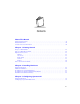
Contents About This Manual Notational Conventions . . . . . . . . . . . . . . . . . . . . . . . . . . . . . . . . . . . . . . . . . . . . . . . . . . . . . . . . . . vii Related Publications . . . . . . . . . . . . . . . . . . . . . . . . . . . . . . . . . . . . . . . . . . . . . . . . . . . . . . . . . . . . . viii Contact and Service Information . . . . . . . . . . . . . . . . . . . . . . . . . . . . . . . . . . . . . . . . . . . . . . . . . . . viii Chapter 1. Getting Started Purpose of This Manual . .
VRC 6940 Product Reference Guide Chapter 4. Installing Software Equipment Required . . . . . . . . . . . . . . . . . . . . . . . . . . . . . . . . . . . . . . . . . . . . . . . . . . . . . . . . . . . . 4-1 Transferring and Installing Application Programs . . . . . . . . . . . . . . . . . . . . . . . . . . . . . . . . . . . . . . 4-2 1. Prepare the PC for Communications and File Downloading. . . . . . . . . . . . . . . . . . . . . . . . . 4-2 2. Provide a Reliable Power Source. . . . . . . . . . . . . . .
Contents Chapter 7. Maintenance Maintaining the Internal Battery. . . . . . . . . . . . . . . . . . . . . . . . . . . . . . . . . . . . . . . . . . . . . . . . . . . 7-1 Storing the Terminal. . . . . . . . . . . . . . . . . . . . . . . . . . . . . . . . . . . . . . . . . . . . . . . . . . . . . . . . . . . . 7-2 Cleaning . . . . . . . . . . . . . . . . . . . . . . . . . . . . . . . . . . . . . . . . . . . . . . . . . . . . . . . . . . . . . . . . . . . . . 7-2 Appendix A.
VRC 6940 Product Reference Guide Appendix C. Keyboard Layouts Keyboard Character & Character Combination Illustrations. . . . . . . . . . . . . . . . . . . . . . . . . . . . . . C-4 Appendix D. Environmental and Technical Specifications Specifications . . . . . . . . . . . . . . . . . . . . . . . . . . . . . . . . . . . . . . . . . . . . . . . . . . . . . . . . . . . . . . . . . Scanner Port . . . . . . . . . . . . . . . . . . . . . . . . . . . . . . . . . . . . . . . . . . . . . . . . . . . . . . . . . .
About This Manual This Product Reference Guide describes the VRC 6940 terminal. Topics include: hardware installation, software configuration, operation, troubleshooting, and maintenance. Notational Conventions This document uses the following conventions: ! “Operator” or “User” refers to anyone using a VRC 6940 terminal. ! “Terminal” refers to a VRC 6940 terminal.
VRC 6940 Product Reference Guide Related Publications ! VRC 6900 Series Quick Reference Guide p/n 72-37640-XX ! Series 3000 Application Programmer's Guide p/n 70-16308-XX ! Series 3000 Application Programmer’s Reference Manual p/n 70-16309-XX ! Series 3000 System Software Manual p/n 70-16310-XX ! Spectrum 24 Network Terminal Technical Reference Guide — Radio Firmware and Driver Guide Version 3 p/n 70-20193-XX ! Spectrum 24 Ethernet Access Point User Guide p/n 70-12057-XX ! Spectrum24 Wireless
About This Manual Symbol Support Center For service information, warranty information or technical assistance contact or call the Symbol Support Center in: United States 1 Symbol Technologies, Inc. One Symbol Plaza Holtsville, New York 11742-1300 1-800-653-5350 Canada Symbol Technologies Canada, Inc.
VRC 6940 Product Reference Guide Germany/Deutchland Symbol Technologies GmbH Waldstrasse 68 D-63128 Dietzenbach, Germany 6074-49020 (Inside Germany) +49-6074-49020 (Outside Germany) Italy/Italia Symbol Technologies Italia S.R.L.
Chapter 1 Getting Started VRC 6940 terminals are rugged mobile computer terminals that communicate by radio with a host computer on Spectrum24® networks. End-users view network applications and data on the terminal’s 8-line screen, and use its keyboard or an attached scanner to enter and transmit data. The terminal uses the DR-DOS ™ V3.41 operating system, compatible with the industrystandard IBM PC-DOS ™. DR-DOS provides access to a number of commercially available programming tools.
VRC 6940 Product Reference Guide Parts of a VRC 6940 Terminal Standard Parts A standard VRC 6940 terminal includes these standard parts: ! Terminal with attached vehicle-mount bracket ! Bracket knobs (2) ! External DC power cable ! Internal PCMCIA radio card for use with a Symbol Spectrum24 network ! VRC 6940 Terminal Quick Reference Guide (p/n 72-37640-XX) Front Antenna (accessory option) Display Screen Bracket Knob Keyboard F1 F2 F3 F4 F5 A B C D E F G 7 8 9 H I J K L M
Getting Started Options and Accessories Options You can also order the VRC 6940 with these options: ! Keyboard backlight ! Internal heating device Accessories You can order these VRC 6940 accessories separately from Symbol: ! Scanner cable ! RS-232 cable ! Primary antenna ! Vehicle-mounted antenna ! Spectrum24® PCMCIA radio card ! AC Universal Power Supply ! AC cable ! DC cable Note: Contact your Symbol Sales representative to order the cable appropriate for your country.
VRC 6940 Product Reference Guide Printers The VRC 6940 terminal can use these Symbol printer models: ! PS 1000 ! PS 200 Before You Use the Terminal... Table 1-1. VRC 6940 Installation and ConfigurationTasks Task 1-4 Where to Find the Instructions Install the hardware in a vehicle or forklift, or on a wall or workbench. See Hardware Installation page 2-2. Provide a primary AC or DC power source. See Providing Power: Vehicle Installations on page 2-5. Charge the internal battery.
Chapter 2 Installing Hardware This chapter describes how to install a VRC 6940 terminal into a vehicle or onto a wall or workbench. Please read all of these instructions before you begin. Caution A properly trained technician must perform the installation. Improper installation can damage your vehicle. Equipment Required Vehicle Mounted VRC 6940 ! an External DC power cable (supplied with terminal). ! minimum of two 3/8” bolts with self-locking nylon nuts. ! a drill with a 7/16” drill bit.
VRC 6940 Product Reference Guide ! a drill with a 7/16” drill bit ! 7/16” hex wrench ! primary or external antenna (optional) Hardware Installation The physical requirements of the work area affect where you place the terminal. There are different installation options, depending on where you plan to locate it. Figure 2-1 shows a terminal mounted on a vehicle. Figure 2-2 shows a terminal mounted on a wall, and Figure 2-3 shows a terminal mounted on a workbench.
Installing Hardware Figure 2-1. Terminal Mounted on a Vehicle Figure 2-2. Terminal Mounted on a Wall F1 F2 A B F3 F4 C D E F G J K L M N 4 Q R S T U 1 Y Z SHIFT FUNC - 0 . H I O P V W X F5 BACK ON/OFF CTRL 7 8 9 5 6 CLEAR 2 3 ENTER Figure 2-3.
VRC 6940 Product Reference Guide 4. Optional: attach a primary antenna to the connector at the top of the terminal, as shown in Figure 2-4. To attach the antenna: a. Place the metal end of the antenna onto the connector. b. Line up the posts with the connector openings and press down gently. c. Twist the bottom ring clockwise to lock it into position. Back of Terminal Antenna Connector Figure 2-4. Attaching a Primary Antenna 5. Optional: install a vehicle-mounted antenna.
Installing Hardware Providing Power: Vehicle Installations VRC 6940 terminals can be powered by: ! 12V or 24V gas-powered vehicles ! battery-powered vehicles, up to 60 volts To provide power to a vehicle-installed VRC 6940: 1. Locate your vehicle’s power source. Always connect a VRC 6940 terminal to a continuous or unswitched power source. 2. Prepare the External DC power cable. One end of the power cable fits into the terminal’s DC Power connector. The other end has no connector (see Figure 2-6).
VRC 6940 Product Reference Guide i. Red power wire ii. In-line fuse holder with 5A slow-blow fuse iii. iv. Twist-on nylon wire connector v. Wrapped wires and fuse holder Figure 2-7. Adding an In-line Fuse Holder b. Route the External DC power cable from the terminal location to the connection point for your vehicle’s power source. See the Installation Note below.
Installing Hardware 3. Prepare the cable termination: Strip 3/8” of insulation from the two wire ends and terminate them with a connector that matches your vehicle’s requirements. See the Installation Note, right, for more information. a. Connect the red wire to the vehicle power source. Connect the black wire to a vehicle ground wire or chassis ground. b. Connect the External DC power cable to your vehicle power source.
VRC 6940 Product Reference Guide Installation and the Internal Battery A VRC 6940 terminal has an internal battery that powers the terminal if there is a temporary interruption, disconnection, or fluctuation in the main DC or AC power. We recommend that you save all data and close all applications before removing a terminal’s main power supply. You cannot use the internal battery to operate the terminal. A terminal’s internal battery may be depleted when you first install it.
Chapter 3 Configuring Spectrum24 Each VRC 6940 terminal has a Spectrum24 radio card that must be configured before the terminal can communicate with a Spectrum24 network. This chapter describes how to do this. For more information on Spectrum24 radio communications, see Spectrum24 Network Terminal Technical Reference Guide — Radio Firmware and Driver Guide Version 3 (p/n 7020193-XX).
VRC 6940 Product Reference Guide Configuring a Spectrum24 Radio Card To configure a Spectrum24 radio card. 1. Provide a reliable power source. If you have not already done so, install the terminal hardware and provide a reliable power source as described in Chapter 2. If the terminal is mounted in a vehicle, it can remain mounted as long as the internal battery is fully charged (see page 2-8) and you can position it close enough to the host PC for the cables to reach.
Configuring Spectrum24 3. Set Spectrum24 configuration parameters. The CFG24 Configurator utility lets you set Spectrum24 parameters in a text file on the RAM disk (D:\net.cfg). It also saves the parameters in a buffer in flash memory on the radio card. The radio driver and TCP/IP stack get their configuration parameters from net.cfg. Table 3-1 summarizes Spectrum24 parameters. For more information on setting parameters, see CFG24 Configurator Utility on page A-12.
VRC 6940 Product Reference Guide Table 3-1. Spectrum24 Configuration Options Option Description Diversity Determines how many antenna ports the radio will attempt to use for communications. Match this setting to the number of antennas you’re using. MU Sleep Mode If you set MU Sleep Mode to On, the radio stays on even if an application powers down the terminal because of inactivity. The default setting is On. Boot Mode Indicates the source of the terminal’s IP address.
Configuring Spectrum24 4. When you finish setting Spectrum24 parameters, warm boot the terminal: a. Press the ON/OFF key to suspend the terminal. b. Press and hold the SHIFT and L keys. c. Press and release the ON/OFF button. d. Release the SHIFT and L keys. " The terminal reloads the system drivers and attempts to associate with a Spectrum24 AP. " If the radio card is configured correctly, it tries to locate a bootp server, fails, and boots to a DOS prompt.
VRC 6940 Product Reference Guide 3-6
Chapter 4 Installing Software This chapter describes how to install application programs onto a terminal. VRC 6940 terminals have a number of drives available for storing user applications and data. For more information on available drive space, the software environment and a list of standard VRC 6940 software, see Appendix B, Software Environment. Before you begin, read the procedures in this chapter all of the way through.
VRC 6940 Product Reference Guide Transferring and Installing Application Programs This section describes how to transfer a HEX image from a Host PC onto a VRC 6940 terminal over a standard RS-232 null modem cable. The procedure uses the SENDHEX or WINHEX program on the Host PC and the Program Loader utility on the VRC 6940. The Program Loader installs the HEX image by converting the ASCII data stream into files that are stored in non-volatile memory (NVM) on the terminal (the application EEPROM).
Installing Software parameters, and press ENTER. The example in Figure 4-2 shows a baud rate of 38400, and the COM2 option. For pgmname, type the name of the HEX file you are transferring, without the .hex extension. The default parameter values are: " 9600 bps " COM1 " 7 data bits " Odd parity " Xon/Xoff flow control C:\>cd\ sendhex pgmname 38400 com2 SENDHEX Command HEX File Name (no .hex extension) COM Port Baud Rate Figure 4-2.
VRC 6940 Product Reference Guide 2. Provide a Reliable Power Source If you have not already done so, install the terminal hardware and provide a reliable power source, as described in Chapter 2. If the terminal is mounted on a vehicle, it can remain mounted as long as the internal battery is fully charged (see page 2-8) and you can position it close enough to the Host PC for the cables to reach.
Installing Software 3. Press UP or DOWN arrows to scroll through Command Mode options until you see the Program Loader option. Then press ENTER to display the message shown in Figure 4-5. Program Loader WARNING: EEPROM WILL BE ERASED CONTINUE? Figure 4-5. Erasing NVM (EEPROM) 4. When you are ready to erase EEPROM, press ENTER. This message appears: Program Loader Erasing EEPROM Please wait.... The program erases the EEPROM and prompts you for communications parameters.
VRC 6940 Product Reference Guide b. Data Bits: Select 7. The screen will look like this: Comm Parameters Data Bits 7 Figure 4-7. Setting Data Bits on the VRC 6940 c. Parity: Select Odd. The screen will look like this: Comm Parameters Parity Odd Figure 4-8. Setting Parity on the VRC 6940 d. Flow Control: Select Xon/xoff. The screen will look like this: Comm Parameters Flow Control Xon/xoff Figure 4-9. Setting Flow Control on the VRC 6940 6.
Installing Software 4. Start the File Transfer 1. On the Host PC, press ENTER to start the transfer. The Host PC displays this message: C:>\ Bytes sent = xxxx xx% If the Host PC is not ready or the cable is disconnected between the PC and the terminal, the PC displays this message: Awaiting DSR In this case, check the cable connection and then press ENTER again on the Host PC to start the download. 2.
VRC 6940 Product Reference Guide Successful File Transfer Following a successful file transfer, the files must be copied to the flash disk before you can use them. This happens the next time the terminal is re-initialized (cold booted). See 5. Complete the Installation of Transferred Files , next. 5. Complete the Installation of Transferred Files To complete the installation of transferred files, you must re-initialize (cold boot) the terminal. To do this: 1.
Chapter 5 Operating a VRC 6940 After you install and configure a VRC 6940 terminal for your facility, you can release it for use.
VRC 6940 Product Reference Guide Powering a Terminal On and Off A terminal must be connected to a main power supply (e.g., a vehicle battery). If you remove this power supply, the terminal suspends and cannot be turned on again until you reconnect the power. An internal battery maintains data while the terminal is suspended, but it cannot be used to operate the terminal. Save all your data and close all applications before removing a terminal’s main power supply. See page 2-8 for more information.
Operating a VRC 6940 Powering On or Off Automatically Particular applications may cause a VRC 6940 to power on or off automatically. This can be controlled by application programming or default configuration settings.
VRC 6940 Product Reference Guide Modifier Keys: SHIFT, FUNC and CTRL SHIFT, FUNC, and CTRL are modifier keys that generate a special character or function. For example, you might press FUNC, J to brighten the display. To do this: 1. Press and release the FUNC key. 2. Press and release the J. 3. The display brightens and the keyboard returns to normal functioning. Use modifier keys individually or in combinations.
Operating a VRC 6940 Table 5-1. Special Key Sequences Function Access Method Description SHIFT SHIFT key After you press SHIFT, the next key you press appears in uppercase (for an alpha key), or as a punctuation mark or symbol (for a number key). CAPS LOCK FUNC, L Places the whole keyboard into Caps Lock mode. Press FUNC, L again to cancel this feature. FUNC FUNC key A function key used to invoke special keyboard functions. CTRL CTRL key A control key used to generate control characters.
VRC 6940 Product Reference Guide Adjusting Brightness Task Key Sequence Brighten the screen. FUNC, J Darken the screen. FUNC, I Toggle the keyboard backlight on or off. FUNC, K Comment There are seven levels of brightness. Repeat the key sequence to reach the desired level of brightness. Not all terminals include a keyboard backlight option. Entering Data To enter data or issue commands, use the terminal’s keyboard, or attach a scanner (see Figure 5-4).
Operating a VRC 6940 Bar Code Scanning Attaching an External Bar Code Scanner 1. Press the ON/OFF key to suspend the terminal. 2. Remove the plug cover from the scanner port on the back of the terminal, shown in Figure 5-4. 3. Fit the scanner’s connector plug into the connector. Align the red dot on the end of the scanner cable with the red dot on the terminal’s scanner connector. 4. Press the ON/OFF key to power the terminal on. Back of Terminal Scanner Port Figure 5-4.
VRC 6940 Product Reference Guide Moving a Terminal to a Different Power Source To move a VRC 6940 terminal from one power source to another: 1. Save any data you are working with, and close all applications. 2. Press the ON/OFF key to suspend the terminal. 3. Make sure a power source is ready in the new location. 4. Unplug the external power cable from the power connector on the back of the terminal. 5. Remove the terminal from its current mounting. 6. Move the terminal to the new location and mount it. 7.
Chapter 6 Troubleshooting This chapter provides basic problem-solving information for VRC 6940 terminals, including: ! troubleshooting and error messages ! warm and cold boot instructions ! running the Memory Transfer utility to provide more troubleshooting data Troubleshooting a VRC 6940 Terminal Table 6-1 describes some problems, their probable causes and some suggested solutions. Some of the situations are discussed further in the pages that follow. Table 6-1.
VRC 6940 Product Reference Guide Table 6-1.Troubleshooting VRC 6940 Terminals Problem Start-up process fails Action The terminal may be out of range of the Access Point (AP) and unable to communicate with the host computer. Move the terminal closer to the AP and try starting it again. If one of these messages appears: Boot server doesn’t exist. Boot server not configured for this terminal. 1. The bootp server may not be running. Check the bootp server. 2. The radio may not be functioning.
Troubleshooting Table 6-1.Troubleshooting VRC 6940 Terminals Problem Action Scanner laser works but does The bar code may not be legible. Try scanning another label of the not read bar codes same product, or type in the data manually. The scanner window may be dirty or severely scratched. If it is dirty, clean it with a soft, dry cloth moistened with an ammoniabased glass cleaner. If the scanner window is badly scratched, replace the scanner.
VRC 6940 Product Reference Guide Scanning Problems Scanning may not work correctly if: ! the scanner has not been configured, or is configured incorrectly ! a contact wand scanner has been moved over the bar code too slowly, too quickly or at an uneven speed ! a contact wand scanner has been moved diagonally across the bar code ! a bar code scanner was held at the wrong angle or distance from the bar code ! the scanner window is dirty or severely scratched ! labels are smudged ! labels are too
Troubleshooting 3. Restart After Forcing a Suspend If you have forced the terminal into suspend, do not use the ON/OFF key to restart the terminal, as this causes the program to resume where it left off, trying to perform the same unsuccessful operation. 1. First, try to start the terminal with a warm boot, described on page 6-5. 2. If a warm boot does not correct the problem, try a cold boot, described on page 6-6. 3.
VRC 6940 Product Reference Guide Cold Boot A cold boot fully resets the system and clears memory, including the RAM disk. It resets the software and allows you to restart applications. Any unsaved RAM data will be lost. Programs and data that have been stored in memory or on the RAM Disk are deleted. NonVolatile Memory (NVM) is not affected. To perform a cold boot: 1. Press the ON/OFF key to suspend the terminal. 2. Press and hold the ENTER, F4 and F1 keys. 3. Press and release the ON/OFF key. 4.
Troubleshooting Command Mode To boot to Command Mode: 1. Press the ON/OFF key to suspend the terminal. 2. Press and hold the A and D keys. 3. Press and release the ON/OFF key. 4. Release the A and D keys. This terminal displays this screen: COMMAND MODE Select Function Self Test Figure 6-1. Command Mode screen 5. Use the UP or DOWN arrows to display other options in place of Self Test. When the option you want appears, press ENTER to select it.
VRC 6940 Product Reference Guide Memory Transfer Analyzer (MTA) Utility The VRC 6940 has a Memory Transfer Analyzer (MTA) utility for application troubleshooting. It runs from Command Mode. Programmers can analyze applications using RCVHEX.EXE on a PC and the MTA on the VRC 6940. For more information on RCVHEX.EXE, see the Series 3000 Application Programmer’s Guide (p/n 70-16308-XX). The MTA transmits data from a VRC 6940 to the Host PC. You may transfer all of the memory, or a selected range.
Troubleshooting C:\>rcvhex memory.txt 38.4 1 RCVHEX Command Filename to receive data (you can make one up) Baud Rate COM Port Figure 6-2. Setting up to Receive a Memory Transfer 4. Boot the VRC 6940 to Command Mode: a. Press and hold the A and D keys. b. Press and release the ON/OFF key. c. Release the A and D keys. d. The terminal boots to the function selector screen in Command Mode, as shown in Figure 6-3. Press UP or DOWN arrows to scroll through the options.
VRC 6940 Product Reference Guide 7. Select a range of RAM to transfer. Press the UP and DOWN arrows to select an option (All, Range or None) and press ENTER. If you select All, the program skips to the summary screen. Continue at step 10. RAM Select Option All Figure 6-4. Selecting a Range of Memory toTransfer 8. Specify a range of RAM by setting Start and End addresses. Use LEFT and RIGHT arrow keys to move the cursor to a digit that you want to set. Use UP and DOWN arrow keys to change the value.
Troubleshooting 10. If the VRC 6940 has EMS, use the arrow keys to specify the range to transfer. This prompt only appears if EMS is installed. Then press ENTER. EMS Use arrow keys Start End Figure 6-7. Selecting a Range of EMS toTransfer 11. The terminal displays the ranges you selected. Verify that they are correct. Figure 68 shows an example of what you might see. If the values are correct, press ENTER. If the values are not correct, press CLEAR to clear the fields, then select new values.
VRC 6940 Product Reference Guide 13. Start the Memory Transfer. Make sure the Host PC is ready to receive data, and then press ENTER on the VRC 6940. While memory data is transferring, the VRC 6940 displays a report of the 1 KB range being transferred. The screen updates for every 1024 bytes (1 KB) of memory. Memory Transfer Sending: 0D40 Figure 6-9. MemoryTransfer Status Screen 14. Check the transmission results. When the transmission has completed, a status screen appears.
Chapter 7 Maintenance A VRC 6940 terminal requires minimal maintenance. However, as with any electronic device, proper use and care will increase its life. This chapter provides basic maintenance instructions including: ! maintaining the internal battery ! storing the terminal ! cleaning Maintaining the Internal Battery The VRC 6940 has an internal NiMh battery designed to maintain session data while the terminal is disconnected from its main power supply (e.g.
VRC 6940 Product Reference Guide Storing the Terminal If you are storing the terminal, keep the internal battery charged by connecting the terminal to a main power supply with the terminal in suspend. If you store the terminal with no main power supply, the internal battery runs down. Before you can use the terminal, you will need to charge the internal battery. See Maintaining the Internal Battery on page 7-1.
Appendix A Utilities and Diagnostic Tests VRC 6940 terminals include two sets of diagnostic applications: ! Self Test diagnostics let you view current hardware settings and run basic diagnostic tests. See page A-2 for instructions on running the Self Tests. ! DIAG24 diagnostics that allow you to ping the network and troubleshoot possible radio problems. See page A-12 for information on running the DIAG24 utility.
VRC 6940 Product Reference Guide VRC 6940 Self Tests Run the Self Tests if you suspect a problem with the terminal’s hardware. They test the terminal’s hardware components to make sure they are working correctly. To run the Self Tests, first boot to Command Mode: 1. Suspend the terminal. 2. Press and hold the A and D keys. 3. Press and release the ON/OFF key. 4. Release the A and D keys. The terminal displays the screen shown here: COMMAND MODE Select Function Self Test Figure A-1.
Utilities and Diagnostic Tests 7. To end a Self Test and return to the Self Test menu, press CLEAR. To return to the Command Mode function menu, press CLEAR again. Table A-1. Self Test Summary Self Test What You Should See Config Screen 1 Config Screen 1 Vers: 6940 1.
VRC 6940 Product Reference Guide Keyboard Test The Config Screen 1 Self Test lets you test any keys except CLEAR and the ON/OFF key. When you press a key, the program displays the corresponding key code to the right of the Config Screen 1 test name on the top line. Table A-2 shows the codes for each key. Table A-2.
Utilities and Diagnostic Tests DIAG24 Diagnostics Utility The DIAG24 Diagnostics utility lets you ping an Access Point (AP) on the network as a way to identify possible problems with wireless network communication. DIAG24 has two options, with the same series of set-up menus for both options. DIAG24 Setup To run the utility and set up for the tests: 1. Boot the terminal to a DOS prompt. The DOS prompt appears if you boot the terminal and it cannot connect to the network. 2.
VRC 6940 Product Reference Guide Note: DIAG24 uses a message file (msg.msg) that it reads from the same drive and directory as the DIAG24 software. If you see corrupted screens, the message file may be missing. 4. Select a Roaming Mode. If you want the terminal to ping anAP, but roam between APs as you move around, select Roaming Enabled. If you want to ping a specific AP, select that AP identifier from the list. If more APs are in range than can fit on one screen, then the last selection will be More.
Utilities and Diagnostic Tests 6. Press 1, 2, 3 or 4 to select the number of pings you want to perform: NUMBER OF PINGS 1. 100 pings 2. 500 pings 3. 1000 pings 4. Non-stop Select[1-4 or 'Q']: Figure A-6. Selecting the Number of Pings 7. Press 1 or 2 to determine whether or not errors will cause the terminal to beep: BEEP MODE 1. Beep on error 2. Silent Select[1-2 or 'Q']: Figure A-7.
VRC 6940 Product Reference Guide Ping Test During the AP Ping Test the terminal displays and updates this screen: Error Count Association Indicator Ping Test Count Access Point ID AP PING TEST A Cnt Err AP RS 56 0 18 36 57 0 18 36 58 0 18 36 59 1 18 36 TMO 60 1 18 36 Press ‘Q’ to Quit RSSI Indicator Indicates an error Figure A-8. The AP Ping Test Table A-4 describes the field contents. The reports wrap so that the last five message reports are visible.
Utilities and Diagnostic Tests When the test stops, the terminal displays a summary screen: AP PING TEST Total secs = 7.4 RF Secs = 6.7 Pings = 100 Packet size = 100 Timeouts = 4 [R]epeat or [Q]uit Figure A-9. Sample AP Ping Test Results Screen The summary shows: ! the elapsed time of the test ! total pings transmitted ! packet size used ! retry count ! number of timeouts To repeat the test with the same parameters, press R. Press Q or CLEAR to end the test and return to the DIAG24 menu.
VRC 6940 Product Reference Guide Field Diagnostic Test During the Field Diagnostic Test the terminal displays and updates this screen: Error Count Retry Count Association Indicator Ping Test Count Timer AP PING TEST A Cnt Err Rty ms AP 56 0 0 165 18 57 0 0 55 18 58 1 1 TMO 18 59 1 0 220 18 60 1 0 58 18 Press ‘Q’ to Quit Access Point ID Figure A-10. The Field DiagnosticTest Table A-5 describes the field contents. The reports wrap so that the last five message reports are visible.
Utilities and Diagnostic Tests When the test stops, the terminal displays a summary screen: FIELD DIAGNOSTICS Total secs = 8.2 RF Secs = 4.9 Pings = 100 Packet size = 100 Timeouts = 4 [R]epeat or [Q]uit Figure A-11. The Field Diagnostic Test Results Screen The summary shows: ! the elapsed time of the test ! total pings transmitted ! packet size used ! retry count ! number of timeouts To repeat the test with the same parameters, press R.
VRC 6940 Product Reference Guide CFG24 Configurator Utility The CFG24 Spectrum24 Configurator utility lets you: ! configure radio communication parameters ! initialize a configuration stored in the NET.CFG file in the terminal’s current directory CFG24 updates NET.CFG settings every time it runs. It saves parameter settings to the radio flash storage initialization area, and then checks for an association between the terminal and an Access Point (AP).
Utilities and Diagnostic Tests The Configurator Menu The Configurator menu appears the first time you start the terminal, or if you launch the CFG24 program without parameters. Figure A-12 shows Configurator menu options. Note that some terminals do not allow you to change the Subnet Mask, Default Router, and Terminal IP addresses. If you are using Spectrum24 802.11 protocolbased software, the menu shows the ESS ID option. For Spectrum24 Spring protocolbased software, the menu shows Net ID.
VRC 6940 Product Reference Guide ESS ID or Net ID An ESS or Net ID identifies a radio network and differentiates between radio networks. All equipment on one network must use the same ESS or Net ID. Spectrum24 terminals can support the Spectrum24 802.11 or Spectrum24 Spring protocols. The menu displays the ESS ID or Net ID, depending on which protocol you are using. Terminals using Spectrum24 with the 802.11 protocol require an ES SID. The ES SID is a a 32-character alphanumeric value.
Utilities and Diagnostic Tests SUBNET MASK Enter SN Mask: 255.255.255.0 BkSp, CLR, Enter Figure A-15. Setting a Subnet Mask Default Router The Default Router address is the node address that receives all packets destined for remote networks. To configure the Default Router: 1. Select Default Router to display the screen shown in Figure A-16. 2. Erase all or part of the entry. 3. Type an IP address in decimal using the ddd.ddd.ddd.ddd format. 4. Press CLEAR or ENTER to return to the main menu.
VRC 6940 Product Reference Guide Terminal IP Address If a boot server is not allocating IP addresses, you can set a Terminal IP Address: 1. Select MU IP Address to display the screen shown in Figure A-17. 2. Erase all or part of the entry. 3. Type an IP address in decimal using the ddd.ddd.ddd.ddd format. 4. Press CLEAR or ENTER to return to the main menu. MU IP ADDRESS Enter IP address: 0.0.0.0 BkSp, CLR, Enter Figure A-17. Setting aTerminal IP Address Diversity To configure Diversity: 1.
Utilities and Diagnostic Tests MU Sleep Mode If you set MU Sleep Mode On, the radio stays powered on when the rest of the terminal powers down because of inactivity. You can wake the terminal by sending a message directly to it, but broadcast messages will not wake it. If you set the switch Off, the radio powers off if the rest of the terminal powers down because of inactivity. The default setting is On. To configure MU Sleep Mode: 1. Select MU Sleep Mode to display the screen shown in Figure A-19. 2.
VRC 6940 Product Reference Guide Boot Mode Options: Boot Broadcasts a TCP/IP BOOTP request to the network. If they have been configured to do so, boot servers on the network send a response. The terminal accepts the first valid response it receives, which contains a terminal IP address and other network parameters that override any parameters entered through CFG24. DHCP Uses the same process as the Boot option but uses the Dynamic Host Configuration Protocol.
Utilities and Diagnostic Tests Buffers To configure the terminal Buffers: 1. Select Buffers to display the screen shown in Figure A-22. 2. Use the UP or DOWN arrow keys to select 4, 8,or 12, then press ENTER. 3. Press CLEAR or ENTER to return to the main menu. BUFFERS Enter Buf Cnt: 8 BkSp, CLR, Enter Figure A-22. Configuring the Buffers Re-Transmit Delay To configure the Re-Transmit Delay: 1. Select ReXmit Delay to display the screen shown in Figure A-23. 2.
VRC 6940 Product Reference Guide Rate Control To configure the Rate Control: 1. Select Rate Control to display the screen shown in Figure A-24. 2. Use the UP or DOWN arrow keys to select 1Mb only, 2Mb only, or 1Mb and 2 Mb options, then press ENTER. For Spring protocol, 1Mb is the only choice. RATE CONTROL TX Rate: 1 MB only BkSp, CLR, Enter Figure A-24. Setting the Rate Control Scanner/RF Operation To configure the Scanner/RF operation: 1. Select Scan/RF Op to display the screen shown in Figure A-24. 2.
Utilities and Diagnostic Tests Flash Utility The flash.bat utility lets you copy, delete or rename files on the flash disk: it switches the flash disk to write mode, performs the operation, and then returns the flash disk to read-only mode. The LWP software copies flash.bat onto the E:\ drive the first time you start the terminal. Deleting To delete a named file from the current directory of the flash disk: flash del filename.
VRC 6940 Product Reference Guide A-22
Appendix B Software Environment This section describes the software environment for a VRC 6940 terminal. A VRC 6940 has four drives as described in Table B-1: Table B-1. VRC 6940 Drives Drive Size Type Contents A:\ 256 Kb Flash, EPROM This drive contains: • BIOS, including the Command Mode menus and commands and Self-Test software • Essential system drivers • DOS B:\ 256 Kb Flash, EEPROM This drive is the main space for user applications. For the first installation, it contains theLWP hex image.
VRC 6940 Product Reference Guide Table B-1. VRC 6940 Drives Drive E: Size 1MB Type Flash Contents This drive is normally read-only, although it can be controlled by application programming on drive B. The LWP hex image copies these utilities into this space: • BOOTP • CFG24 • DIAG24 • FLASH.BAT Boot Sequence The first time a new terminal powers up: 1. A:\config.sys loads drivers. 2. A:\autoexec.bat calls and runs B:\autoexec.bat. 3. B:\autoexec.bat loads the application files contained in the LWP.
Software Environment LAN WorkPlace (LWP) Software All VRC 6940 terminals have a copy of LWP.HEX loaded at the factory. The first time you start the terminal, it installs the utilities listed below onto the E:\drive. CFG24 The CFG24 Configurator utility that allows you to configure the Spectrum24 radio. You can run it from a DOS prompt. See page A-12 for more information. DIAG24 The DIAG24 Diagnostics utility that allows you to run Access Point ping tests. You can run it from a DOS prompt.
VRC 6940 Product Reference Guide Table B-2. VRC 6940: Software Files Directory A:\ (cont’d) B:\ D:\ E:\ B-4 File Name Description 2WAY3000.SYS A Series 3000 Protocol Device Driver. For more information, see the Series 3000 System Software Manual (p/n 70-16310-XX). S1.BIN A Spectrum One radio driver. CONFIG.SYS A configuration file that loads essential drivers and files. It loads A:\shell.com COMMAND.COM A command batch file. AUTOEXEC.BAT Loads the application files contained in the LWP.
Software Environment Table B-2. VRC 6940: Software Files Directory E:\ (cont’d) File Name Description APPINIT.COM Scans the flash disk for valid applications. If it finds more than one, it displays an application selection menu. A valid RF application has a home directory in the flash disk’s root directory containing a file called RUN.BAT. This is how the system knows which applications are present, and which are batch applications. CBT.COM Utility to re-initialize (cold boot) the terminal. WBT.
VRC 6940 Product Reference Guide Table B-2. VRC 6940: Software Files Directory E:\ (cont’d) B-6 File Name Description TDREM.EXE Remote end of serial link used to transfer files to and from a terminal. Used mainly during development but also a useful diagnostic tool. FLASH.BAT A flash utility for copying, renaming or deleting files from flash memory. Useful in development for transferring single files to flash disk. See page A-21 for more information. RAMINIT.EXE Copies _AP.BAT to new RAM disk.
Software Environment Table B-2. VRC 6940: Software Files Directory E:\ (cont’d) File Name Description FGET.BAT Batch file for doing TFTP file transfers from a server to the flash disk. If the transfer fails it is retried. The server IP address is picked up from the environment variable SIADDR, which is set up by BOOTP.COM if either a BOOTP or DHCP process is performed. UPDATE.BAT Batch file used for an over-the-air software update facility.
VRC 6940 Product Reference Guide B-8
Appendix C Keyboard Layouts This section describes the characters and character sequences produced by the 54-key keyboard using the default translation tables. Table C-1 displays the information in table format. Figures C-1 to C-10 show keyboard illustrations. These key definitions can be changed by application programs.
VRC 6940 Product Reference Guide Table C-1.
Keyboard Layouts Table C-1.
VRC 6940 Product Reference Guide Keyboard Character & Character Combination Illustrations The captions indicate what sequence of modifier keys produce the keyboard character. FUNC and SHIFT-FUNC key combinations (Figure C-5 and Figure C-9) produce scan codes, ASCII values, and printable characters/logical key sequence names. The keys are illustrated as follows: Scan Code (decimal) SS AA C ASCII Value (decimal) Printable Character or Logical Key Sequence Name Figure C-1.
Keyboard Layouts Shift F1 Shift F2 Shift F3 Shift F4 Shift F5 BACK ON/OFF CTRL 4 6 8 A B C D E F G & * ( 2 H I J K L M N $ % ^ CLEAR O P Q R S T U ! @ # ENTER V W X Y Z _ ) > Figure C-3.
VRC 6940 Product Reference Guide 64 00 F6 56 00 65 48 a 59 00 98 111 Dark 25 29 45 112 55 00 67 32 42 100 100 BckLt* 113 53 47 18 101 58 19 114 r 21 57 32 Space 33 102 00 CapLk 68 121 00 44 ON/OFF 34 103 f F10 y / 00 F10 e Light 16 68 d q * 00 F9 102 p - 00 F8 c 101 o 74 66 b F1 24 00 F7 00 Alt 41 96 g 67 00 F9 20 29 16 t 69 00 13 61 00 26 91 43 40 00 End 43 92 93 39 51 39 45 82 - 59 44 53 47 00
Keyboard Layouts F1 F2 F3 F4 F5 BACK O N/OFF CTRL A B C D E F G 7 8 9 H I J K L M N 4 5 6 CLEAR O P Q R S T U 1 2 3 ENTER V W X Y Z FUNC _ 0 . Ctrl Home Ctrl End Ctrl Pgup Ctrl \ Ctrl Pgdn Figure C-7.
VRC 6940 Product Reference Guide 89 00 Shft F6 56 00 90 48 A 84 00 Shft F1 24 79 O 74 00 Shft F7 66 B 91 00 Shft F8 29 00 92 00 Shft F9 32 C 68 101 100 Light BckLt* 25 16 19 45 81 Q ? 82 21 69 57 32 Space 33 70 CapLk 93 00 Shft F10 89 Y 44 ON/OFF 34 F 58 00 R 53 63 - 00 E Dark 80 18 D 101 P 93 Shft F10 92 00 84 T 69 00 41 126 43 55 13 43 27 125 39 58 } : 51 12 60 95 82 48 Figure C-9.
Appendix D Environmental and Technical Specifications This appendix describes: ! physical, environmental, and operational information for VRC 6940 terminals ! reference information for the COM1 and scanner ports ! mappings for the null modem pinouts Specifications Table D-1 summarizes physical, operational, and environmental specifications for the VRC 6940. Table D-1. VRC 6940 Specifications Dimensions 12” x 9” x 3" / 310 mm x 234 mm x 81 mm (LxWxD) Weight 6.
VRC 6940 Product Reference Guide Table D-1. VRC 6940 Specifications Microprocessor NEC V25 Housing Magnesium Alloy Sealing IP65 and NEMA4 Vibration Specification SAE 1445 Operating Temperature: without internal heater -2°F to 122° F / -20°C to 50° C with optional internal heater -22°F to 122°F / -30°C to 50°C Storage Temperature -40°F to 140° F/ -40°C to 60° C RF Technology: 2.4 GHz Yes Operating System DR-DOS Architecture 16 Bit Memory: RAM FLASH 640KB 1.
Environmental and Technical Specifications COM1 Serial Port The COM1 Serial Port is located on the back panel of the VRC 6940. Table D-3 lists the pin descriptions. Table D-3.
VRC 6940 Product Reference Guide Null Modem A null modem cable is used for: ! downloading programs from a PC to a VRC 6940 terminal ! unloading memory contents from a VRC 6940 terminal to a PC The cable has a 16-pin male circular connector, and a 25-pin female D-Connector. Table D4 shows the pin-outs for both connectors. Table D-4.
Appendix E Communications Status Codes Communications Status Codes When the Program Loader and Memory Transfer utilities complete their functions, they return communication status codes in the form of a four hexadecimal number. A status code of 0000 indicates success; any other code indicates failure. Table E-1 describes the conditions associated with the status codes. Table E-1.
VRC 6940 Product Reference Guide E-2
Glossary Access Point A device that provides transparent access between Ethernet wired networks and IEEE 802.11 interoperable radio-equipped mobile units (MUs). Symbol’s hand-held computers, or other devices equipped with a PCMCIA slot, communicate with wired networks using Access Points (AP). The mobile unit may roam among the APs in the same subnet while maintaining a continuous, seamless connection to the wired network. Refer to Subnet. AP See Access Point. API Application Programming Interface.
VRC 6940 Product Reference Guide Baud Rate A measure for data transmission speed. BIOS Basic Input Output System. A collection of ROM-based code with a standard API used to interface with standard PC hardware. Bit Binary digit. One bit is the basic unit of binary information. Generally, eight consecutive bits compose one byte of data. The pattern of 0 and 1 values within the byte determines its meaning. Bits per Second (bps) Number of bits transmitted or received per second. BOOTP Bootstrap protocol.
Glossary DOS Disk Operating System. This is basic software that allows you to load and use software applications on your computer. VRC 6940 terminals use a product called DR-DOS. DR-DOS Disk operating system software on VRC 6940 terminals. It is compatible with and extends the industry-standard IBM PC-DOS, and provides access to a number of commercially available programming tools. EEPROM Electrically Erasable Programmable Read-Only Memory. An on-board non-volatile memory chip. See NVM.
VRC 6940 Product Reference Guide I/O Ports Input/Output Ports. The I/O ports are primarily dedicated to passing information into or out of the terminal’s memory. The VRC 6940 terminal includes a Serial port and a Scanner port. IP Address A 32-bit address assigned to nodes on a TCP/IP network. The address is written as four octets separated by periods (dotted decimal format), e.g., 130.24.34.03. They represent a network section, an optional subnet section, and a host section. Also see Terminal IP Address.
Glossary Parity A technique for verifying whether or not data has been lost or overwritten when it is transferred from one place in storage to another or between computers. PCMCIA Personal Computer Memory Card Interface Association. PCMCIA Card A plug-in expansion card for laptop computers and other devices, also called a PC Card. PC Cards are 85.6 mm long x 54 mm wide, and have a 68 pin connector. There are several different kinds: Type Height Common Use Type I 3.
VRC 6940 Product Reference Guide Scanner An electronic device used to scan bar code symbols and produce a digitized pattern that corresponds to the bars and spaces of the symbol. Its three main components are: 1. Light source (laser or photoelectric cell) - illuminates a bar code. 2. Photodetector - registers the difference in reflected light (more light reflected from spaces). 3. Signal conditioning current - transforms optical detector output into a digitized bar pattern.
Glossary Transmission Control Protocol/Internet Protocol (TCP/IP) A suite of standard network protocols that were originally used in UNIX environments but are now used in many others. The TCP governs sequenced data; the IP governs packet forwarding. TCP/IP is the primary protocol that defines the Internet. VRC Vehicular Radio Computer.
VRC 6940 Product Reference Guide Glossary-8
Index A Accessories (optional) . . . . . . . . . . . . . . . 1-4 Alt + Func-modified keyboard . . . . . . . . . C-8 Alt-modified keyboard . . . . . . . . . . . . . . C-6 Antenna, vehicle-mounted option . . . . . . . 2-4 AP ping test . . . . . . . . . . . . . . . . . . A-5, A-8 Applications, installing . . . . . . . . . . . . . . 4-2 B Backlight, keyboard . . . . . . . . . . . . . . . . 5-6 Booting boot mode . . . . . . . . . . . . . . . . . . . . 3-4 cold . . . . . . . . . . . . . . . . . . . . . . . .
VRC 6940 Product Reference Guide Display adjusting brightness . . . . . . . . . . . . . 5-6 blank . . . . . . . . . . . . . . . . . . . . . . . 6-2 washing . . . . . . . . . . . . . . . . . . . . . . 7-2 Diversity . . . . . . . . . . . . . . . . . . . . . . . . 3-4 E EEPROM, erasing with Program Loader . . 4-5 802.11 protocol . . . . . . . . . . . . . . . . . . A-14 Entering data . . . . . . . . . . . . . . . . . . . . . 5-6 Equipment, optional . . . . . . . . . . . . . . . . 1-3 Error messages . . . . .
Index O ON/OFF key . . . . . . . . . . . . . . . . . . . . . Operation entering data . . . . . . . . . . . . . . . . . . power on suspend or off . . . . . . . . . . Options . . . . . . . . . . . . . . . . . . . . . . . . . S 5-2 5-6 5-2 1-3 P Parts accessories . . . . . . . . . . . . . . . . . . . . 1-3 options . . . . . . . . . . . . . . . . . . . . . . 1-3 standard . . . . . . . . . . . . . . . . . . . . . 1-2 Ping test . . . . . . . . . . . . . . . . . . . . A-5, A-8 Power changing power sources . . .
VRC 6940 Product Reference Guide Terminal accessories . . . . . . . . . . . . . . . . . . . . 1-3 configurator utility . . . . . . . . . . . . .A-12 initial use . . . . . . . . . . . . . . . . . . . . . 1-4 parts (illus.) . . . . . . . . . . . . . . . . . . . 1-2 preparing for file transfer . . . . . . . . . . 4-4 restart after forced power off . . . . . . . 6-5 Troubleshooting . . . . . . . . . . . . . . 6-1–6-12 application not responding . . . . . . . . . 6-3 blank display . . . . . . . . . . . . . . .
VRC 6940 Product Reference Guide 72-37641-02 Revision B — June 2001 2 Symbol Technologies, Inc. One Symbol Plaza, Holtsville N.Y.