WS 2000 Wireless Switch System Reference WS 2000 Wireless Switch Version 1.0 72E-67701-01 Rev A March 2004 www.symbol.
Copyright Copyright © 2004 by Symbol Technologies, Inc. All rights reserved. No part of this publication may be modified or adapted in any way, for any purposes without permission in writing from Symbol Technologies, Inc. (Symbol). The material in this manual is subject to change without notice. Symbol reserves the right to make changes to any product to improve reliability, function, or design.
WS 2000 Wireless Switch System Reference Guide Table of Contents Chapter 1. Overview............................................................................................ 6 WS 2000 Wireless Switch System Reference Guide ....................................................6 About this Document .............................................................................................6 Document Conventions .........................................................................................
WS 2000 Wireless Switch System Reference Guide Mobile Unit Access Control List (ACL) ................................................................37 Step 7: Configure Access Ports...................................................................................37 Step 8: Configure Subnet Access ...............................................................................39 The Access Overview Table................................................................................
WS 2000 Wireless Switch System Reference Guide Chapter 7. A Field Office Example .................................................................. 111 Background................................................................................................................111 The Plan ....................................................................................................................112 Configuring the System Settings ......................................................................
WS 2000 Wireless Switch System Reference Guide Chapter 1. Overview WS 2000 Wireless Switch System Reference Guide This guide is intended to support administrators responsible for understanding, configuring and maintaining the Wireless Switch. This document provides information for the system administrator to use during the initial setup and configuration of the system. It also serves as a reference guide for the administrator to use while updating or maintaining the system.
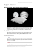
System Overview GUI Screen text Indicates monitor screen dialog / output from the graphical user interface accessed from any web browser on the network. System Overview The WS 2000 Wireless Switch provides a low-cost, feature-rich wireless switch for sites with one to six Access Ports. The WS 2000 Wireless Switch works at the center of a network’s infrastructure to seamlessly and securely combine wireless LANs (WLANs) and wired networks. The switch sits on the network.
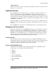
Hardware Overview Hardware Overview The WS 2000 Wireless Switch provides a fully integrated solution for managing every aspect of connecting wireless LANs (WLANs) to a wired network. This wireless switch can connect directly to a cable or DSL modem, and can also connect to other wide area networks through a Layer 2/3 device (such as a switch or router). It includes the following features: • One WAN (RJ-45) port for connection to a DSL modem, cable modem, or any other Layer 2/3 network device.
Software Overview Power Specifications • Maximum Power Consumption: 90-256 VAC, 47-63 Hz, 3A • Operating Voltage: 48 VDC • Operating Current: 1A • Peak Current: 1.6A Environmental Specifications • Operating Temperature: 0ºC to 40ºC • Storage Temperature: -40ºC to 70ºC • Operating Humidity: 10% to 85% Non-condensing • Storage Humidity: 10% to 85% Non-condensing • Operating Altitude: 2.4 km • Storage Altitude: 4.
Software Overview Gateway Services Gateway services provide interconnectivity between the Cell Controller and the wired network, and include the following: • System management through a web-based Graphical User Interface (GUI) and SNMP • 802.1x RADIUS client • Security, including Secure Sockets Layer (SSL) and Firewall • Network Address Translation (NAT), DHCP services, and Layer 3 Routing Copyright © 2004 Symbol Technologies, Inc. All Rights Reserved WS 2000 Wireless Switch: 1.
802.11a Support Chapter 2. Features 802.11a Support 802.11 is a family of specifications for wireless local area networks (WLANs) developed by a working group of the Institute of Electrical and Electronics Engineers (IEEE). The four current specifications include: 802.11, 802.11a, 802.11b, and 802.11g. All four use the Ethernet protocol and carrier sense multiple access with collision avoidance (CSMA/CA) for path sharing, which allows a number of network users to pass packets on the network simultaneously.
Access Ports The 802.11b standard, also called Wi-Fi (Wireless Fidelity), is backward compatible with 802.11. 802.11b uses complimentary code keying (CCK) modulation to provide higher data speeds (up to 11 Mbps) with less multipath-propagation interference. 802.11b operates at the 2.4 to 2.5 GHz range. The WS 2000 Wireless Switch fully supports the 802.11b specification for association with Symbol’s suite of compatible Access Ports and mobile units (MUs).
Gateway Services Gateway Services Network Address Translation (NAT) NAT provides the translation of an Internet Protocol (IP) address within one network to a different, known IP address within another network. One network is designated the private network, while the other is the public. NAT provides a layer of security by translating local, private network addresses to one or more global, public IP addresses through a corporate firewall.
Layer 3 Routing DHCP Client and Server The WS 2000 Wireless Switch can act as a DHCP client on the WAN and each of its three subnets. It also act as an independent DHCP server on each of the three subnets. Layer 3 Routing Overview The WS 2000 Wireless Switch provides Layer 3 routing support to the Network Address Translation (NAT) and Firewall modules. Layer 3 refers to a network layer that selects routes and quality of service based on knowing the address of the neighboring nodes in the network.
WEP 64 (40-bit key) WEP 64 (40-bit key) Wired Equivalency Privacy (WEP) uses a key, or string of case-sensitive characters, to encrypt and decrypt data packets transmitted between a mobile unit (MU) and the WS 2000 Wireless Switch. The administrator configures mobile units (MUs) and the WS 2000 Wireless Switch to use the same key. WEP encrypts the wireless transmissions, but still allows communication among compatible wireless LAN clients and MUs from third-party manufacturers that are 802.11b certified.
802.1x with Shared Key Authentication The pair-wise master keys (PMK) generated by this negotiation are used to generate keys used in MAC encryption. In the absence of a RADIUS server, 802.1x is used in a preshared key configuration. Administrators configure the master key statically through the configuration or the key is obtained through negotiation from an external RADIUS server in compliance with 802.1x.
KeyGuard-MCM Support When a Kerberos-enabled mobile unit (MU) authenticates with WS 2000 Wireless through an Access Port, the switch initially performs Kerberos authentication, even though the Kerberos server exists as a separate entity on the wired LAN. On initial request from a Kerberos-enabled MU, the WS 2000 Wireless Switch acts as a proxy to the external KDC.
Getting Started Overview Chapter 3. Getting Started Getting Started Overview Installing the Switch To install the WS 2000 Wireless Switch hardware, follow the directions in the WS 2000 Wireless Switch Quick Installation Guide found in the box with the switch and on the CDROM that is distributed with the switch.
Getting Started Overview 4. Log in using “admin” as the username and “symbol” as the password. 5. If the login is successful, the following prompt will be displayed. Enter a new admin password in both fields, and click the Update Password Now button. 6. Once the admin password has been updated, the System Settings screen is displayed. Copyright © 2004 Symbol Technologies, Inc. All Rights Reserved WS 2000 Wireless Switch: 1.
Getting Started Overview 7. Enter a System Name for the wireless switch. The specified name appears in the lower-left corner of the configuration screens, beneath the navigation tree. This name can be a useful reminder if multiple Symbol wireless switches are installed. 8. Enter a text description of the location of the switch in the System Location field. This text is used as a reminder to the network administrator and is also used to set the location variable if the switch is administered using SNMP. 9.
Step 1: Configure the LAN Interface Configuring the Switch Once the switch is installed, perform the rest of the basic configuration and setup process as indicated in the following procedures. The links go to pages that have detailed information about the particular configuration step.
Step 1: Configure the LAN Interface Defining the Subnets Select LAN under the Network Configuration group from the left menu. Use the LAN configuration screen to view a summary of physical-port addresses and Wireless LANs (WLANs) associated with the three supported subnets, and to enable or disable each configured subnet. 1. In the LAN screen, the administrator can enable one, two or three subnets. Check the checkbox to the left of the subnet to enable a subnet.
Step 2: Configure Subnets Field Description Interfaces The Interfaces field displays which of the six physical LAN ports are associated with the subnet. The possible ports are: P1 (port 1), P2, P3, P4, P5, and P6 (from left to right facing the front of the switch). The administrator assigns a port to a subnet to enable access to the device(s) connected to that port. The administrator can assign a port to only one subnet. The Interfaces field also lists the WLANs that are associated with the subnet.
Step 2: Configure Subnets 3. Set the Network Mask for the IP address. A network mask uses a series of four numbers that are expressed in dot notation, similar to an IP number. For example, 255.255.255.0 is a network mask. Select a port or WLAN from the Interfaces drop-down menu to associate it with the subnet. Six LAN ports are available on the switch. Assign from one to six ports to a subnet. Two subnets cannot use the same port. However, multiple ports can be assigned to one subnet.
Step 2: Configure Subnets Advanced DHCP Settings 1. Click the Advanced DHCP Server button to display a sub-screen to further customize IP address allocation (on right). 2. Specify the address of a Primary DNS server. The Internet Server Provider (ISP) or a network administrator can provide this address. A DNS server translates a domain name, such as www.symbol.com, into an IP address that networks can use. 3. Specify the address of a Secondary DNS server if one is available. 4.
Step 3: Configure the WAN Interface 5. Use the Static Mappings table to associate static (or fixed) IP addresses with MAC addresses of specific wireless devices. Every wireless, 802.11x-standard device has a unique Media Access Control (MAC) address. This address is the device’s hard-coded hardware number (shown on the bottom or back). An example of a MAC address is 00:09:5B:45:9B:07.
Step 3: Configure the WAN Interface • The host router or switch on the WAN is communicating with the WS 2000 Wireless Switch using DHCP. • The switch is interfacing with an Internet Service Provider (ISP) that uses DHCP addressing. Note: This setting is independent from the DHCP settings for the switch’s internal subnets. 3. It is not necessary to specify the IP Address or any of the other fields on the top section of this form when the WS 2000 wireless switch is set as a DHCP Client.
Step 4: Enable Wireless LANs (WLANs) 4. Check Keep Alive to instruct the switch to continue occasional communications over the WAN even when client communications to the WAN are idle. Some ISPs terminate inactive connections, while others do not. In either case, enabling Keep-Alive mode keeps the switch’s WAN connection alive, even when there is no traffic. If the ISP drops the connection after so much idle time, the switch automatically reestablishes the connection to the ISP. 5.
Step 4: Enable Wireless LANs (WLANs) Wireless Summary Area The top portion of the window displays a summary of the WLANs that are currently defined. This is the screen in which the administrator can enable or disable a WLAN. At first, three WLANs will be listed WLAN1, WLAN2, and WLAN3; however, only WLAN1 will be enabled. 1. To enable either WLAN2 or WLAN3 check the appropriate checkboxes to the left of the WLAN name.
Step 5: Configure WLANs Access Port Adoption Use this list to adopt detected Access Ports and to assign them to a particular WLAN. The switch can adopt up to six Access Ports at a time, but the list of allowed Access-Port addresses (displayed in this area) can exceed six in number. A dual-radio 802.11a/b Access Port counts as one Access Port with respect to the maximum allowed; however, each radio will be listed as a separate Access Port.
Step 6: Configure WLAN Security Within the WLAN window, the administrator changes both standard and advanced configuration features of the WLAN. Field Description Name Rename the WLAN in this field, if desired. Character spaces are allowed. This change affects several other screens and the interface will also change the name in the left menu tree. Symbol Technologies recommends the use of descriptive names for WLANs. ESSID Specify an Extended Service Set Identification (ESSID) for the WLAN.
Step 6: Configure WLAN Security Setting the Authentication Method The authentication method sets a challenge-response procedure for validating user credentials such as username, password, and sometimes secret-key information. The WS 2000 Wireless Switch provides two methods for authenticating users: 802.1x EAP and Kerberos. The administrator can select between these two methods.
Step 6: Configure WLAN Security Kerberos Authentication secret-key cryptography. Using this protocol, a client can prove its identity to a server (and vice versa) across an insecure network connection. After a client and server use Kerberos to prove their identity, they can encrypt all communications to assure privacy and data integrity. 1. Select the Kerberos radio button to enable Kerberos authentication. 2. Click the Kerberos Configuration button to display a sub-screen for authentication settings.
Step 6: Configure WLAN Security 4. When finished, click the OK button to close this screen. 5. Specify a Pass Key and click the Generate button. The pass key can be any alphanumeric string. The switch, other proprietary routers, and Symbol cards in mobile units (MUs) use an algorithm to convert an ASCII string to the same hexadecimal number, but this conversion is not required for a wireless connection. 6. Use the Key #1-4 fields to specify key numbers that use 26 hexadecimal characters.
Step 6: Configure WLAN Security 3. Check the Broadcast Key Rotation checkbox to enable or disable the broadcasting of encryption-key changes to mobile units. 4. Specify a time period in seconds for broadcasting encryption-key changes to mobile units. Set key broadcasts to a shorter time interval (at least 300 seconds) for tighter security on this WLAN’s wireless connections. Set key broadcasts to a longer time interval (at most, 80,000 seconds) to relax security on wireless connections. 5.
Step 6: Configure WLAN Security KeyGuard-MCM KeyGuard-MCM is a proprietary encryption method developed by Symbol Technologies. KeyGuard is Symbol’s enhancement to WEP encryption and can work with any WEP device. This encryption method rotates WEP keys for devices that support the method. This encryption implementation is based on the IEEE Wireless Fidelity (Wi-Fi) standard, 802.11i. 1. Select the KeyGuard-MCM radio button to enable the KeyGuard-MCM encryption method. 2.
Step 7: Configure Access Ports Mobile Unit Access Control List (ACL) Use this list to specify which mobile units can or cannot gain access to the WLAN. The list employs an adoption rule for allowing or denying specific mobile units by way of exception. 1. Select Allow or Deny from the pull-down list. This rule applies to all mobile units except those listed in the table.
Step 7: Configure Access Ports • Radio type—This field indicates the wireless protocol that the Access Port follows. The WS 2000 Wireless Switch supports 802.11b and 802.11 a/b dual-radio Access Ports. • Physical port—This field specifies the physical LAN port on the switch to which the Access Port is connected.
Step 8: Configure Subnet Access 6. From this screen, the administrator can change several pieces of information about each Access Port. Field Description Name Administrators can change the names of the Access Ports from Access Port# to something much more descriptive so that they can easily identify which Access Port is being referenced in the various screens and in the left menu. The name is limited to a string of 13 characters. Location This field is a memory aid for the administrator.
Step 8: Configure Subnet Access The Access Overview Table In the overview table, each of the rectangles represents a subnet association. The three possible colors indicate the current access level, as defined, for each subnet association. Color Access Type Description Green Full Access No protocol exceptions (rules) are specified. All traffic may pass between these two areas. Yellow Limited Access One or more protocol rules are specified.
Step 8: Configure Subnet Access 1. Click in a cell of the table that represents the subnet-to-subnet (or subnet-to-WAN) relationship to define. All access rules (if any are defined) appear in the table in the lower-half of the screen. 2. Use the pulldown menu above the list Allow or Deny all the entries specified in the exception table. You cannot allow some protocols (or ports) and deny others. 3. From the list of checkboxes on the left side, select those protocols to allow or deny.
Step 8: Configure Subnet Access • Select a transport type from the Transport column’s pulldown menu. The available transports are: Transport Description ALL This selection designates all of the protocols displayed in the table’s pull-down list, as described below. TCP Transmission Control Protocol (TCP) is a set of rules used with Internet Protocol (IP) to send data as message units over the Internet.
WLAN—How to Configure Advanced Settings Chapter 4. Advanced Configuration WLAN—How to Configure Advanced Settings The lower section of the WLAN screen provides several settings that the administrator might need to modify; however, the default settings are usually sufficient for most installations. 1. Check the Disallow MU to MU Communications checkbox to enable a communication block between mobile units (MUs) using this WLAN.
WLAN—Setting Default Access Port Settings 5. Use the Multicast Address 1 and Multicast Address 2 to specify one or two MAC addresses to be used for multicast applications. Some VoIP devices make use of multicast addresses. This mechanism ensures that the multicast packets for these devices are not delayed by the packet queue. 6. Click the Apply button to save changes. WLAN—Setting Default Access Port Settings The WS 2000 Network Switch can support up to six Access Port.
WLAN—Setting Default Access Port Settings 5. Check the Antenna Diversity checkbox to enable Antenna Diversity if the Access Port has an external antenna. Antenna Diversity should only be enabled if the Access Port has two matching external antennas. 6. Check the Support Short Preamble checkbox to allow the Access Port to communicate with the MUs using a short 56-bit preamble. A preamble is the beginning part of a frame.
WLAN—Setting Default Access Port Settings 8. Set the beacon values as indicated in the table below. Beacon Interval A beacon is a packet broadcast by the adopted access ports to keep the network synchronized. Included in a beacon is information such as the WLAN service area, the access-port address, the broadcast destination addresses, a time stamp, and indicators about traffic and delivery such as a DTIM. Specify a beacon interval in units of 1,000 microseconds (K-us).
WLAN—Advanced Access Port Settings Primary WLAN Set the Primary WLAN field when the 802.11a broadcast protocol is used. When a WLAN is associated with a 801.11a broadcaster only one ESSID can be broadcast from the Access Port (even though three are supported by the switch) . This field specifies which ESSID to broadcast. Security Beacon Select the Security Beacon checkbox if the WLAN associated with the Access Port needs to be secure. If this feature is selected, the WLAN will not broadcast the ESSID.
WLAN—Advanced Access Port Settings The advanced Access Port settings are found at the bottom of the screen. For most installations, the default settings for the advanced settings are appropriate. 1. Select either Indoors or Outdoors from the Placement pop-up menu. The setting will affect the selection available for several of the other advanced settings. 2. Select a channel number from the Channel drop-down list on which the Access Port should communicate with associated MUs.
WLAN—Advanced Access Port Settings 8. Set the Access Port beacon settings by clicking on the Beacon Settings button. The following window appears. 9. Set the beacon values as indicated in the table below. Beacon Interval A beacon is a packet broadcast by the adopted access ports to keep the network synchronized.
Gateway—How to Configure Network Address Translation (NAT) Primary WLAN Set the Primary WLAN field when the 802.11a broadcast protocol is used. When a WLAN is associated with a 801.11a broadcaster only one ESSID can be broadcast from the Access Port (even though three are supported by the switch) . This field specifies which ESSID to broadcast. Security Beacon Select the Security Beacon checkbox if the WLAN associated with the Access Port needs to be secure.
Gateway—How to Configure Network Address Translation (NAT) This screen displays the IP addresses specified in the WAN screen (Network Configuration --> WAN from the left menu). Up to eight WAN addresses can be associated with the switch. The NAT screen enables the administrator to set of the type of translation and port forwarding required. 2. For each of the addresses, the select the NAT type. • Select 1 to 1 from the pull-down menu to map a WAN IP address to a single local (subnet) IP address.
Gateway—How to Configure the WS 2000 Firewall Gateway—How to Configure the WS 2000 Firewall The WS 2000 Wireless Switch provides a secure firewall / Network Address Translation (NAT) solution for the WAN uplink. The firewall includes a proprietary CyberDefense Engine to protect internal networks from known Internet attacks. It also provides additional protection by performing source routing, IP unaligned timestamp, and sequence number prediction.
Gateway—How to Configure the WS 2000 Firewall Configurable Firewall Filters The administrator can enabled or disabled the following filters. By default, all these filters are activated. If it reasonable to turn off the filters if one of the following things is true: • The switch is on a completely isolated network with no access to the Internet and is therefore secure. • The switch is heavily loaded a slight increase in performance outweighs the safety of the network.
Gateway—How to Configure Static Routes MIME Flood Attack Check A MIME flood attack uses an improperly formatted MIME header in “sendmail” to cause a buffer overflow on the destination host. • Use the Max Header Length field to set the maximum allowable header length. Set this value to be at least 256 bytes. • Use the Max Headers field to set the maximum number of headers allowed. Set this value to be at least 12. Click the Apply button to save changes made on this screen.
Gateway—How to Configure Static Routes Defining Routes The User Defined and RIP Routes area of the screen allows the administrator to view, add or delete internal static (dedicated) routes, and to enable or disable routes that are generated using the Routing Information Protocol (RIP). If RIP is enabled, this table can also include routes that RIP generates. This table also includes internal static routes that the administrator adds.
Security—How to Configure 802.1x EAP Authentication RIP v2 (v1 compat) RIP version 2 (compatible with version 1) is an extension of RIP v1’s capabilities, but it is still compatible with RIP version 1. RIP version 2 increases the amount of packet information to provide the a simple authentication mechanism to secure table updates. RIP v2 RIP version 2 enables the use of a simple authentication mechanism to secure table updates.
Security—How to Configure 802.1x EAP Authentication 3. Click the 802.1x EAP Configuration button to display a sub-screen for specific authentication settings. 4. Check the Enable Reauthentication check box to enable this authentication method. 5. Set the EAP reauthentication period to match the appropriate level of security. A shorter time interval (~ 30 seconds or longer) provides tighter security on this WLAN’s wireless connections.
Security—How to Configure 802.1x EAP Authentication 6. Set the maximum number of retries (Max. Retries) for a client to successfully reauthenticate after failing to complete the EAP process. If the mobile unit fails the authentication process in specified number of retries, the switch will terminate the connection to the mobile unit. 7. The administrator is required to specify the IP address of a primary RADIUS server for this type of authentication to work.
Security—How to Configure Kerberos Authentication Security—How to Configure Kerberos Authentication Kerberos provides strong authentication method for client/server applications by using secret-key cryptography. Using this protocol, a client can prove its identity to a server (and vice versa) across an insecure network connection. After a client and server use Kerberos to prove their identity, they can encrypt all communications to assure privacy and data integrity. 1.
Security—How to Specify a Network Time Protocol (NTP) Server Security—How to Specify a Network Time Protocol (NTP) Server Network Time Protocol (NTP) manages time and clock synchronization in a network environment. The switch, which acts as an NTP client, periodically synchronizes its clock with a master clock on an NTP server.
System Administration Chapter 5. System Administration Overview The WS 2000 Network Management System provides several screens for administering the switch and monitoring activity on the switch.
System Administration Location Description Lower LED This LED is only present on Ports 1-4. These ports provide 802.3af Power over Ethernet (PoE) support to devices (such as Access Ports). The LED has several states: ! OFF — A non-power device (or no device) is connected; no power is being delivered ! GREEN — The switch is delivering 48 volts to the power device connected to that port. ! RED — There was a valid PoE connection; however, the switch has detected that the power device is faulty.
System Administration Change the Location and Country Settings of the WS 2000 When the administrator first logs into the WS 2000 Network Management System, the System Settings screen appears. One of the fields in this screen is the Country field. This field is set to the country in which the switch is installed. Setting this field appropriately ensures compliance with national and local laws concerning electromagnetic emissions and the power level of Access Port radio transmissions.
System Administration How to Restart the WS 2000 Wireless Switch During the normal course of operations, the administrator might need to restart or reset the switch. For example, changing certain configuration settings can require restarting the switch for those settings to take effect. 1. Select System Configuration --> System Settings from the left menu. 2. Click the Restart WS 2000 button to restart the switch. A second window appears, asking for confirmation. 3. Select the Restart button.
System Administration Checking for and Downloading Firmware updates The switch administrator should check for firmware updates for the WS 2000 Wireless Switch on a monthly basis, as follows: 1. Select System Configuration --> Firmware Update or Network Configuration --> System Settings from the left menu. 2. Examine the WS 2000 Version field to record the version number of the currently loaded software. It should be something like 1.02-10. 3. Go to the web site http://www.symbol.
System Administration 6. Specify whether the site is on the WAN or is on one of the subnets associated with the switch by selecting the appropriate choice from the drop-down menu to the right of the radio button. 7. Specify the IP address or domain name of the system that has the update file. 8. Specify a Username and Password that will allow the FTP login and access to the file. 9. Click the Perform Update button to initiate the firmware update for the switch. 10.
System Administration To Import or Export Settings to an FTP Site Use the following procedure for exporting the switch’s configuration settings. 1. Specify the name of the log Filename to be written to or read from the FTP server. 2. Specify the Server IP address of the FTP server to which the log file will be imported or exported. 3. Specify the Username to be used when logging in to the FTP server.
System Administration How to Restore Default Configuration Settings Although it should not be necessary during the normal course of operations, the administrator might need to return to the default configuration settings of the switch. To do so, see the directions below: 1. Consider saving the current configuration settings. See “Exporting and Importing Wireless Switch Settings” for directions on how to save the settings. 2. Select System Configuration --> System Settings from the left menu. 3.
System Administration Restoring Default Configuration Settings Using the Command Line Interface Although it should not be necessary during the normal course of operations, the administrator might need to restore the default configuration settings of the switch.
System Administration Remote Administration How to Configure SNMP Traps The Simple Network Management Protocol (SNMP) facilitates the exchange of management information between network devices. SNMP allows an administrator to manage network performance, find and solve network problems, and plan for network growth. The WS 2000 Wireless Switch includes SNMP management functions for gathering information from its network components, and communicating that information to specific users.
System Administration 1. To create a new community definition, click the Add button in the SNMP v1/v2c Community Configuration area. 2. Specify a site-appropriate name for the community. 3. Use the OID (Object Identifier) pull-down list to select either All or Custom. If All is selection, the community has access to all the OIDs (SNMP parameters) in the SNMP Management Information Base (MIB) file. If Custom is selected, the administrator can allow access to specific OIDs in the MIB to certain communities.
System Administration Setting Up the Access Control List To set up the Access Control list as specified by a range of IP addresses, click the SNMP Access Control button at the bottom of the SNMP Access screen. The SNMP Access Control screen appears: 1. Click the Add button to create a new entry in the Access Control table. 2. Specify the IP address for the user(s) that have access. Enter an IP address only in the Starting IP Address column to specify an address for a single SNMP user.
System Administration SNMP Traps MU Traps AP Traps 3. Check the traps to enable. Trap Category Trap Name Generates a Trap when… SNMP Traps Cold Start The switch’s router reinitializes while transmitting, possibly altering the agent’s configuration or protocol entity implementation. SNMP ACL violation An SNMP client cannot access SNMP management functions or data due to an Access Control List (ACL) violation.
System Administration Trap Category Trap Name Generates a Trap when… MU Traps MU associated An MU becomes associated with one of the switch’s Wireless Local Area Networks (WLANs). MU unassociated An MU becomes unassociated with (or gets dropped from) one of the switch’s WLANs. MU denied association Check this box to generate a trap when an MU cannot associate with the switchmanaged network. A denial of service can result from an absent or incorrectly specified MAC address on a WLAN Security screen.
System Administration Setting the Trap Configuration for SNMP V3 To set the trap notification destination for the SNMP v3 servers, add one or more entries to SNMP v3 Trap Configuration table. 1. Click the Add button to add a new entry to the table. 2. Specify a Destination IP addresses for the systems that will receive notification when an SNMP trap is generated. 3. Specify a destination User Datagram Protocol (UDP) port for receiving the traps that are sent by SNMP agents.
System Administration Configure Management Access The WS 2000 Network Management System runs from a standard Web browser. Any individual on an enabled subnet or over the WAN can access the log screen by specifying one of the IP addresses associated with the user interface. The WS 2000 Access screen allows the administrator to restrict access from different locations.
System Administration Setup AirBEAM Software Access Symbol’s AirBEAM software suite is a comprehensive set of mobility management tools that maximize the availability, security and effectiveness of a wireless network. The fields in this section of the screen allow the administrator to enable access from the AirBEAM software suite and to set the AirBEAM password. 1. To enable AirBEAM access, check the Enable AirBEAM checkbox. 2. Specify a password for AirBEAM software access.
System Administration There are four areas on the screen. The Information area shows general information about the Access Port. The Received and Transmitted areas of the screen display statistics for the cumulative packets, bytes, and errors received and transmitted through the Access Port. The Associated Mobile Units section lists the MUs and provides information on specific MUs that are currently transmitting through the Access Port.
System Administration Received and Transmitted Tables The Received and Transmitted areas of the screen display statistics for the cumulative Access Port statistics, since the Access Port was last adopted or the switch was last rebooted.
System Administration The Received and Transmitted portions of the screen display statistics for the cumulative packets, bytes, and errors received and transmitted through the access port for the associated mobile unit since it last gained access to the switch-managed network. Field Description WLAN Association Indicates the WLAN that is associated with the mobile unit. PSP Mode Under normal circumstances a switch will terminate a connection with a mobile unit if it doesn’t exchange packets regularly.
System Administration The Information portion of the Subnet Stats screen displays general information about the subnet. • The HW address is the Media Access Control (MAC) address of the switch’s WAN port, which is set at the factory. • The IP addresses displayed here for the subnet connection are set on the subnet screen (Network Configuration --> WLAN --> ).
System Administration Transmitted Field Description TX Errors The total number of errors including dropped data packets, buffer overruns, and carrier errors that fail on outbound traffic TX Dropped The number of data packets that fail to get sent from the subnet TX Overruns The total number of buffer overruns (when packets are sent faster than the subnet can handle them) TX Carrier The total number of TCP/IP data carrier errors received Interfaces The interfaces section of the screen displays info
System Administration The Information portion of the WAN Stats screen displays general information about the WAN. Much of this information is generated from settings on the WAN screen in the Network Configuration area. • The Status field displays “Enabled” if the WAN interface is currently enabled on the WAN screen (Network Configuration --> WAN). If the WAN interface is disabled on the WAN screen, the WAN Stats screen does not display connection information and statistics.
System Administration Transmitted Field Description TX Overruns The total number of buffer overruns (when packets are sent faster than the WAN interface can handle them) TX Carrier The total number of TCP/IP data carrier errors received Setting Up and Viewing the System Log The WS 2000 Network Management System keeps a log of the events that happen on the switch. The switch has a modest of amount of memory to store events.
System Administration Setting Up a Log Server To keep a complete history of the events that are logged by the switch, the administrator needs to set up an external system log on a server. The server listens for incoming switchgenerated syslog messages on a UDP port (514 by default), and then decodes the messages into a log file appropriate for viewing and printing. Events are categorized into eight levels (0 through 7), with the lowest numbers representing the most critical issues. 1.
Retail Use Cases Chapter 6. Retail Use Cases Background In the past, CCC clothing stores have used POS terminals with a 10BaseT Ethernet connection to an in-house server. Management has decided to install wireless networking in the stores. Wireless point of sale (POS) terminals and printers will allow them to be more flexible with store layout. Wireless handheld terminals for inventory and price lookup will make inventory faster and more accurate.
Retail Use Cases The Plan Clarisa is the employee assigned to implement the new network in San Jose. She needs three very different security policies. Wireless security policies are part of a WLAN configuration, so she will need three different WLANs. • WLAN #1: Confidential information, such as credit card numbers and customer purchases, will travel over the links to wireless POS terminals. For these, she wants the strongest security measures possible.
Retail Use Cases Configuring the System Settings Contacting the Wireless Switch Clarisa sets up a direct network link between her laptop and the switch, plugging the cable into one of the local, non-WAN, ports. The switch defaults to having all the LAN ports on the first subnet and that subnet having an IP address of 192.168.0.1. So, as far as this connection is concerned, the switch comes up with an initial IP address of 192.168.0.1. She sets her laptop to have an IP address of 192.168.0.
Retail Use Cases Clarisa starts her web browser and enters “http://192.168.0.1/” as the URL. The WS 2000 sends a login page to her browser. She logs in using “admin” for the username and “symbol” as the password. Entering the Basic System Settings Clarisa selects System Settings in the left menu, located under the System Configuration heading. The System Name is used to distinguish between WS 2000 switches for remote configuration. She gives the switch a descriptive name, “SanJose-1”.
Retail Use Cases Setting Access Control In the WS 2000 Access screen, Clarisa controls which network interfaces can be used to reconfigure the WS 2000 switch. She is currently using HTTP access on port 80 over the LAN, so she leaves that on. She wants to be able to manage the switch from corporate headquarters, but she does not want to leave the standard HTTP port, port 80, open over the WAN. She elects to leave port 443 open over the WAN instead.
Retail Use Cases Clarisa clicks the Apply button to save her changes. Clarisa leaves the rest of the System Configuration screens for now, moves to the left menu, and clicks the “+” to the left of Network Configuration so that she can begin to define the subnets. Configuring the Subnets The IP Address Plan Now Clarisa needs to name and define the subnets. The subnet menu items are under the LAN item in Network Configuration in the WS 2000 left menu.
Retail Use Cases And for each subnet: 192.168.**.1 The subnet itself 192.168.**.2 to 192.168.**.10 Static IP addresses 192.168.**.11 to 192.168.**.254 DHCP-supplied IP addresses on the subnet With this plan, she can begin to configure the individual subnets Configuring POS Subnet Clarisa selects the first subnet from the LAN menu items in the left menu. Clarisa renames this subnet “POSsn”, and then gives it an IP address of 192.168.0.1 and a subnet mask of 255.255.255.0.
Retail Use Cases The Default Gateway is already set to the subnet address. This is the IP address to which the DHCP clients on this subnet will forward their outbound traffic. Clarisa fills in the DNS Server addresses that corporate has specified. This will also be supplied to the DHCP clients. The DHCP Lease Time is the time an IP address will remain assigned to a client after there is no more activity. She leave it at the default and clicks Ok to save her changes.
Retail Use Cases After entering the Address Assignment Range, Clarisa clicks Advanced DHCP Server. Copyright © 2004 Symbol Technologies, Inc. All Rights Reserved WS 2000 Wireless Switch: 1.
Retail Use Cases Clarisa enters the DNS server IP addresses and leaves the Default Gateway and DHCP Lease Time at their defaults. She clicks Ok in the Advanced DHCP Server window and then Apply in the Subnet window to save her changes. Now Clarisa will configure the Cafe subnet. Configuring the Cafe Subnet Clarisa selects the third subnet in the LAN menu list under Network Configuration in the left menu. She then renames this subnet “Cafesn” and gives it the IP address 192.168.2.
Retail Use Cases Clarisa clicks Advanced DHCP Server and enters the DNS server IP addresses. The Default Gateway is fine. However, Clarisa expects the cafe patrons to come and go frequently, so she reduces the IP address lease time to 1800 seconds. This means that a DHCP client mobile unit will give up its IP address if it is inactive on the network for more than half an hour. This seems about right for the usage patterns that she expects for the cafe. If she gets complaints, she will bump it to an hour.
Retail Use Cases Clarisa clicks the Ok button in the Advanced DHCP Server window, then on the Apply button in the subnet screen to save her choices. The subnets are now configured. Next Clarisa configures the WAN interface. Configuring the WAN Interface Now Clarisa selects the WAN node in the left menu. Here she enters the static IP address assigned to this store by CCC corporate.
Retail Use Cases If corporate had not paid their ISP for a static IP address for each store, she would have selected the This interface is a DHCP Client option and the WAN configuration information would have been assigned by the ISP each time they connected to the Internet. Clarisa clicks the Apply button to save her changes. Configuring Network Address Translation (NAT) Clarisa has only one public IP address for the whole store.
Retail Use Cases After she makes this selection a new button appears, labeled 1 to Many Mappings. She selects the 1 to Many Mappings button: If Clarisa had more than one static IP address, she would have been able to assign several to the WAN interface. This screen is used to choose how the internal IP addresses on each subnet translated into the selection of external IP addresses. However, she has only one external IP address.
Retail Use Cases Inspecting the Firewall Clarisa selects the Firewall item in the left menu. Each of the checkbox items represents a type of attack the WS 2000 can filter out. She checks to see that all of the options are enabled. Clarisa clicks the Apply button to confirm that all attacks listed will be filtered. Configuring the Access Ports So far, Clarisa has been operating with the WS 2000 connected only to her laptop. To configure the Access Ports, she will need to connect them to the switch.
Retail Use Cases All of the Access Ports will be indoors, so she specifies Placement as Indoors. She leaves Channel set to one and will reset each Access Port to a different 802.11b channel later. She sets the power level to 100mW, the maximum level allowed in the US. She leaves the Slowest Supported Rate and the Fastest Supported Rate as they are. The switch will operate at the maximum rate allowed by radio conditions, scaling back as needed. She sees no reason to change those parameters.
Retail Use Cases In the Access Port Properties section, Clarisa enters a new name for the Access Port and a brief description of its permanent location. In the Advanced Access Port Properties section, Clarisa sets the Channel to 3. She knows that the store uses cordless phones that transmit on channel 1. She also wants to maintain some separation between the channel used by this Access Port and the other Access Ports at this location. She does not change any of the other settings.
Retail Use Cases She clicks the Apply button to save her changes. Configuring the Cafe Access Port Finally, she names the third Access Port “Cafe AP” and sets Channel to 9. In this case she makes sure Support Short Preamble is not selected. There are two preambles in use in the wireless world, an older, longer one and a newer, shorter one. Most wireless devices support both and use the shorter one by default.
Retail Use Cases Again, she clicks the Apply button to save her changes. Associating the Access Ports to the WLANs Now Clarisa selects the Wireless item in the left menu. This screen indicates which Access Ports are associated with which WLANs. First Clarisa looks in the Summary section of the screen to determine that all three WLANs are enabled.
Retail Use Cases Clarisa clicks the Apply button to save her choices. Configuring the WLANs Configuring the Cafe WLAN Clarisa clicks the “+” to the left of the Wireless menu item in the left menu. She selects the third WLAN. This is the WLAN that she plans to use for the cafe WLAN. The WLAN name is used with in the WS 2000 configuration screens to make the interface easier to navigate. She names this WLAN from “WLAN3” to “Cafe”. She also gives it an ESSID of “CCC-Cafe”.
Retail Use Cases She clicks the Apply button to save her choices. Clarisa goes to the left menu and clicks the “+” to the left of the Cafe WLAN node. A menu item labeled Cafe Security appears and Clarisa selects it. She confirms that the Cafe Security screen shows that no authentication and no encryption methods.
Retail Use Cases Clarisa clicks the Apply button to confirm her choices. Clarisa clicks the “+” to the left of the Printer WLAN menu item and selects the Printer Security item. In the screen that displays, Clarisa selects no authentication. She enters the MAC numbers of the wireless printers in the Mobile Access Control section. The MAC numbers are unique numbers assigned to every network-cable hardware device and are usually listed on the same label that shows the device’s model number and serial number.
Retail Use Cases she will configure all of the mobile units on this WLAN with the correct ESSID, so she disallows this option, potentially keeping a cafe customer out of the POS WLAN. The options for Multicast Addresses are designed for compatibility with some VoIP phones. Clarisa does not know if the voice handhelds will require it but, even if they do, she will not know the required multicast addresses until they are purchased and arrive. She leaves the Multicast Addresses blank.
Retail Use Cases For the POS subnet and the Printer subnet, she selects Allow all protocols when going to the WAN, the POS subnet, and the Printer subnet. After specifying all of the subnet access rules, she clicks the Apply button to save her changes. Copyright © 2004 Symbol Technologies, Inc. All Rights Reserved WS 2000 Wireless Switch: 1.
Retail Use Cases Configuring the Clients Clarisa has now finished configuring the switch. Next, she configures the wired clients. Going to each device, she gives it the IP address and other networking information that it will need to communicate with the switch: Client IP Address Subnet Mask Gateway WS 2000 Port Wired POS terminal #1 192.168.0.4 255.255.255.0 192.168.0.1 4 Wired POS terminal #2 192.168.0.5 255.255.255.0 192.168.0.1 5 Server 192.168.0.6 255.255.255.0 192.168.0.
A Field Office Example Chapter 7. A Field Office Example Background Leo is the network administrator, system administrator, and IT professional for a field office with 60 employees. The users include sales people, sales engineers, office administration and customer support people. All of the sales personnel have laptops and many of them have personal digital assistants (PDAs). The office is connected to the Internet and to Corporate through a frame relay link.
A Field Office Example The Plan Each WS 2000 WLAN has exactly one security policy, where a security policy is defined as a user authentication method and a data encryption method. Because each WLAN can have one and only one security policy, WLAN configuration is usually defined by the security needs of the installation. If two groups of users require different security policies, then they must associate to the WS 2000 through different WLANs.
A Field Office Example Configuring the System Settings Contacting the Wireless Switch To begin configuration of the switch, Leo sets up a communication link to the switch. Leo starts with a direct network link between his laptop and the switch, plugging the cable into one of the local, non-WAN, ports. The switch defaults to having all the LAN ports on the first subnet and that subnet having an IP address of 192.168.0.1.
A Field Office Example Leo launches his web browser and enters “http://192.168.0.1/” as the URL. He logs in using “admin” for the username and “symbol” as the password. Entering the Basic System Settings Leo clicks the “+” to the left of System Configuration in the left menu, then selects System Settings in the left menu. The system name is used to distinguish between WS 2000 switches for remote configuration. Leo gives the switch a descriptive name, “Atlanta1”.
A Field Office Example Setting Access Control Leo then clicks the WS 2000 Access node in the left menu. This controls which subnet can be used to reconfigure the WS 2000 switch and how that reconfiguration can be accomplished. Leo will be inside the LAN, so he leaves on all means of reconfiguring from within the LAN. Corporate may want to have read access from outside the LAN, so Leo leaves on SNMP access from the WAN.
A Field Office Example Leo then changes the switch passwords from the default to something relatively secure, something with letters, numbers, and punctuation marks in it. Leo clicks the Update Password Now button to register the password change, then on the Apply button in the WS 2000 Access screen to save all changes. Copyright © 2004 Symbol Technologies, Inc. All Rights Reserved WS 2000 Wireless Switch: 1.
A Field Office Example Configuring the LAN Leo clicks the “+” to the left of Network Configuration in the left menu. It expands and he selects the LAN item. This screen shows the subnets, their IP addresses, and the network interfaces (the 10/100BaseT ports and the WLANs) that are currently associated with each subnet. All of the subnets are enabled; no changes are needed there. Next Leo needs to configure each of the subnets. He clicks the “+” symbol to the left of LAN in the left menu to expand it.
A Field Office Example He also selects the option This interface is a DHCP server. Choosing this DHCP option means that the switch will pick IP addresses from the Address Assignment Range and assign them to network clients on this subnet, as needed. This screen also sets the IP address for the switch’s interface to the subnet. Any address that starts with “192.168” is an internal-use-only IP address.
A Field Office Example There is no reason to set up static DHCP mappings now. These would permanently lease an IP address to a client with a specific MAC address. Leo clicks the OK button on the Advanced DHCP Server window, then the Apply button on the subnet window. Copyright © 2004 Symbol Technologies, Inc. All Rights Reserved WS 2000 Wireless Switch: 1.
A Field Office Example Configuring the Sales Subnet The sales and marketing subnet is configured exactly the same way as the engineering subnet, though with a different name and a different IP address range. Leo selects the Advanced DHCP Server button and follows the same procedures as he did for the engineering subnet. Leo clicks the OK button on the Advanced DHCP Server window, then the Apply button on the subnet window.
A Field Office Example Again, Leo fills out the advanced DHCP screen as he did for the two previous subnets. Leo clicks the OK button on the Advanced DHCP Server window, then the Apply button on the subnet window. The next step is to configure the WAN interface. Configuring the WAN Next Leo configures the WS 2000 WAN interface. This interface connects the WS 2000 switch to the VPN appliance and, through that appliance, to the Internet.
A Field Office Example Leo has three addresses for this switch. He plans to use one address for the traffic from each of the subnets. He selects the More IP Addresses button and enters the other two IP addresses: He clicks Ok button in the address window, then the Apply button on the WAN window to save his changes. The next step is to set up the network address translations (NAT). Copyright © 2004 Symbol Technologies, Inc. All Rights Reserved WS 2000 Wireless Switch: 1.
A Field Office Example Setting Up Network Address Translation After entering the IP addresses for the WAN interface, Leo clicks the “+” left of the WAN item in the left menu to expand it. He then selects the NAT item. The WS 2000 displays the three IP addresses he entered when configuring the WAN. Each of these IP addresses will serve as the alias for all of the traffic from its corresponding subnet. It will serve as the only alias for many internal-only IP addresses.
A Field Office Example Leo clicks any of the NAT Ranges button to the right of the IP addresses. The 1 to Many Outbound Mappings window displays. Leo uses the pull-down menu to set the outbound IP address for each subnet. These are the same as the inbound IP addresses that he specified when he configured the WAN. He clicks the Ok button to save his entries, and then clicks the Apply button in the NAT screen. The next step is to configure the firewall. Copyright © 2004 Symbol Technologies, Inc.
A Field Office Example Confirm Firewall Configuration After setting the NAT ranges, Leo selects Firewall under WAN in the left menu. The WS 2000 displays a series of Firewall Filters, all of which are currently enabled. Leo examines the list and sees no reason to turn off any of the filters. He clicks the Apply button. The next step is to determine which Access Ports each WLAN will use.
A Field Office Example He goes to the section labeled Access Port Adoption List and deselects the check boxes to the right of the row in which the MAC address range is specified as ANY. For the engineering WLAN, Leo selects the Add button, then enters a Start MAC value of 00:A0:00:00:00:01 and an End MAC value of 00:A0:00:00:00:02. Leo selects the WLAN1 and makes sure that the other WLAN checkboxes are not checked. To specify the marketing WLAN, Leo clicks again on the Add button.
A Field Office Example Configuring the WLANs Leo has specified which Access Ports go with which wireless LANs (WLANs). Now, he needs to name and configure each WLAN. He expands the Wireless node in the left menu, and selects the first WLAN listed. Leo gives the WLAN the name “EngWLAN” so that subsequent screens in the WS 2000 interface will be a little easier to read.
A Field Office Example Security The next step is to set security for the engineering WLAN. He selects the “+” to the left of EngWLAN in the left menu to display the EngWLAN Security item. Leo selects that item and the security screen appears. Leo selects 802.1x EAP as the authentication method and WPA-TKIP as the encryption method. Leo also needs to configure the 802.1x EAP system and the WPA-TKIP encryption. Leo clicks 802.1x EAP Configuration.
A Field Office Example Leo clicks the OK button to save the 802.1x EAP settings. Leo then clicks the WPA-TKIP Settings button. WPA-TKIP constantly changes keys, but requires an initial key, known to both ends of the communication. If Leo was not using 802.1X EAP user authentication, that initial key would need to be entered here, in the Key Settings section. However, with 802.1x EAP, the RADIUS server supplies the initial key, so that Key Settings section is grayed out for Leo.
A Field Office Example Leo clicks the OK button to save his WPA-TKIP settings, then the Apply button to confirm the WLAN configuration. This completes configuration of the engineering WLAN. The sales and marketing WLAN and the administration WLAN are configured exactly the same way, with the sole exception that they take different names and ESSIDs.
A Field Office Example He does not change the Antenna Diversity setting, Short Preamble setting, the RTS Threshold, or the Beacon Settings. These parameters control some of the broadcast mechanics of an 802.11 communication between mobile units and Access Ports. In most cases, there is no reason to change them. He clicks Apply to save his choices. After configuring the default Access Port settings, Leo gets four short 100baseT cables and connects the four Access Ports to the switch.
A Field Office Example He sets the channel at 36, and notes the number. Access Ports channels should be separated as much as practical to minimize interference between them. The other engineering Access Port will use channel 48 and the marketing Access Port will use channel 60. He then sets the power level at the maximum setting of 100mW. Leo leaves the Slowest Supported Rate and the Fastest Supported Rate as they are.
A Field Office Example Leo clicks the Apply button to save the configuration for this Access Port. Leo then selects the third Access Port in the left menu. This will be the sales and marketing Access Port. Leo configures it similarly, but uses channel 60. Leo clicks Apply to save his changes. To avoid interference with the sales and marketing AP, Leo chooses channel 149 for the administration Access Port. He then enters the Access Port name and location. Copyright © 2004 Symbol Technologies, Inc.
A Field Office Example Leo clicks the Apply button to save the changes for the administration Access Port. Since all of the Access Ports are 802.11a Access Ports, Leo assigned the channels to minimize cross-channel interference. The channel assignments are listed in the table below: Access Port Channel Engineering Offices 36 Demo Room 48 Sales and Marketing 60 Administration 149 The Access Ports are now configured. The next step is to specify access levels between the subnets.
A Field Office Example Configuring Subnet Access Leo selects the Subnet Access item in the left menu. The subnet access defaults to the configuration that Leo prefers. Every subnet has access to every other subnet and access to the WAN. Leo clicks the Apply button to confirm this configuration. If Leo needed to restrict access in some way, he could select an item in the matrix and specify the restriction.
A Field Office Example He could then enter the user-based or protocol-based restrictions in the EngSN --> WAN section. Since Leo does not need to make any changes, there is nothing more to be done. Installing the Access Ports and Testing The switch is now configured! Leo connects the switch’s WAN port to the VPN appliance that goes to the outside world. He gets three laptops and sets each of them to use DHCP for IP address assignment, 802.
Sample Configuration File Appendix A. Sample Configuration File All of the configuration settings for the WS 2000 Wireless Switch can be saved to a configuration file, and then either imported back into the same switch or transferred to another switch. Below is a sample configuration file that has been annotated using comment lines. All comment lines begin with // and are blue in color. The configuration file is organized by function area, and most areas correspond directly to a menu item.
Sample Configuration File / system ntp // NTP menu set mode disable set server 1 0.0.0.0 set server 2 0.0.0.0 set server 3 0.0.0.0 set port 1 123 set port 2 123 set port 3 123 / system snmp access // SNMP ACL configuration delete acl all // SNMP v1/v2c configuration delete v1v2c all add v1v2c public ro 1.3.6.1 add v1v2c private rw 1.3.6.
Sample Configuration File // WLAN 1 configuration set mode 1 enable set ess 1 101 set enc 1 none set auth 1 none set wep-mcm index 1 1 set wep-mcm enc-key 1 1 c2767fe55c0a564f90f50a3989 set wep-mcm enc-key 1 2 f2464fd56c3a667fa0c53a09b9 set wep-mcm enc-key 1 3 e2565fc57c2a766fb0d52a19a9 set wep-mcm enc-key 1 4 92262fb50c5a061fc0a55a69d9 set kerb user 1 \0 set kerb enc-passwd 1 8e57 set kerb realm 1 \0 set kerb server 1 1 0.0.0.0 set kerb server 1 2 0.0.0.0 set kerb server 1 3 0.0.0.
Sample Configuration File set enc 2 none set auth 2 none set wep-mcm index 2 1 set wep-mcm enc-key 2 1 c2767fe55c0a564f90f50a3989 set wep-mcm enc-key 2 2 f2464fd56c3a667fa0c53a09b9 set wep-mcm enc-key 2 3 e2565fc57c2a766fb0d52a19a9 set wep-mcm enc-key 2 4 92262fb50c5a061fc0a55a69d9 set kerb user 2 \0 set kerb enc-passwd 2 8e57 set kerb realm 2 \0 set kerb server 2 1 0.0.0.0 set kerb server 2 2 0.0.0.0 set kerb server 2 3 0.0.0.
Sample Configuration File set wep-mcm enc-key 3 1 c2767fe55c0a564f90f50a3989 set wep-mcm enc-key 3 2 f2464fd56c3a667fa0c53a09b9 set wep-mcm enc-key 3 3 e2565fc57c2a766fb0d52a19a9 set wep-mcm enc-key 3 4 92262fb50c5a061fc0a55a69d9 set kerb user 3 \0 set kerb enc-passwd 3 8e57 set kerb realm 3 \0 set kerb server 3 1 0.0.0.0 set kerb server 3 2 0.0.0.0 set kerb server 3 3 0.0.0.0 set kerb port 3 1 88 set kerb port 3 2 88 set kerb port 3 3 88 set eap server 3 1 0.0.0.0 set eap server 3 2 0.0.0.
Sample Configuration File set set set set set beacon intvl A 100 rts A 2341 dtim A 10 short-pre A enable primary A 1 // Default 802.11 B radio configuration set reg B in/out 1 100 set rate B 1 11 set div B enable set beacon mode B disable set beacon intvl B 100 set rts B 2341 set dtim B 10 set short-pre B enable / // Access Port configuration network ap delete 1 all delete 2 all delete 3 all / // LAN configuration network lan set mode 1 enable set name 1 Subnet1 set ipadr 1 192.168.0.1 set mask 1 255.
Sample Configuration File / // LAN DHCP configuration network lan dhcp set mode 1 server set dgw 1 192.168.0.1 set dns 1 1 192.168.0.1 set dns 1 2 192.168.0.1 set lease 1 86400 set range 1 192.168.0.100 192.168.0.254 set mode 2 server set dgw 2 192.168.1.1 set dns 2 1 192.168.1.1 set dns 2 2 192.168.1.1 set lease 2 86400 set range 2 192.168.1.100 192.168.1.254 set mode 3 server set dgw 3 192.168.2.1 set dns 3 1 192.168.2.1 set dns 3 2 192.168.2.1 set lease 3 86400 set range 3 192.168.2.100 192.168.2.
Sample Configuration File set mode 6 disable set ipadr 6 0.0.0.0 set mode 7 disable set ipadr 7 0.0.0.0 set mode 8 disable set ipadr 8 0.0.0.0 / network wan fw // Firewall configuration set syn enable set src enable set win enable set ftp enable set ip enable set seq enable set mime filter enable set mime len 8192 set mime hdr 16 / network wan nat // NAT configuration set type 1 1-to-many set outb ip 1 0.0.0.0 set inb mode 1 disable set inb ip 1 0.0.0.0 set type 2 none set outb ip 2 0.0.0.
Sample Configuration File set set set set set set inb mode 7 disable inb ip 7 0.0.0.0 type 8 none outb ip 8 0.0.0.0 inb mode 8 disable inb ip 8 0.0.0.
Sample Configuration File Copyright © 2004 Symbol Technologies, Inc. All Rights Reserved WS 2000 Wireless Switch: 1.
Index Index 104-bit shared key ................................ 15 40-bit shared key .................................. 15 802.11a specification support............... 11 802.11b specification support............... 11 802.1x authentication EAP ............................................ 32, 56 Kerberos ..................................... 16, 59 RADIUS ........................................... 15 shared key......................................... 16 access AirBEAM software ..........................
Index dimensions, physical .............................. 8 downloads, firmware ............................ 65 EAP authentication configuring ....................................... 56 WLANs ............................................ 32 encryption method KeyGuard-MCM .............................. 36 none .................................................. 36 setting ............................................... 33 WEP ................................................. 33 WPA-TKIP.......................
Index defining routes.................................. 55 setting configuration......................... 55 support.............................................. 14 routes, defining..................................... 55 Routing information Protocol.......See RIP rules, access.......................................... 40 security 802.1x EAP authentication............... 56 802.1x Kerberos authentication........ 59 example use cases........................... 128 firewalls.................................
Index 802.1x EAP authentication............... 32 advanced settings........................ 43, 47 configuring ....................................... 30 configuring printer.......................... 106 configuring security.......................... 31 default settings.................................. 44 enabling ............................................ 28 example use cases........... 104, 105, 127 Kerberos authentication ................... 33 no encryption....................................