AP 300 802.
AP 300 Quick Reference Guide FINAL.Not for distribution. Copyright © 2004 SYMBOL TECHNOLOGIES, INC. All rights reserved. All rights reserved. No part of this publication may be modified or adapted in any way, for any purposes without permission in writing from Symbol Technologies, Inc. (Symbol). The material in this manual is subject to change without notice. Symbol reserves the right to make changes to any product to improve reliability, function, or design.
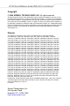
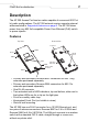
1 FINAL.Not for distribution. Introduction The AP 300 Access Port, a component of the Symbol Wireless Switch System, links wireless 802.11a/b/g devices to the switch, enabling incremental growth of your wireless network with a cost-effective alternative to standard access points. For optimal performance, the AP 300 provides two placement options: wall and ceiling. Wall mount slots fit onto two screws provided. Arrows on the AP 300 case guide placement of the screws.
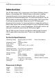
2 AP 300 Quick Reference Guide FINAL.Not for distribution. Radio Characteristics The AP 300 is an IEEE a/b/g-compliant device with the appropriate radio option configured. The table below shows the characteristics for each device compliance. Device Mbps Data Rate Support Utilizing Diversity 802.11a GHz 6, 9, 12, 18, 24, 36, 48, Transmit and 4.9 to 5.875 range and 54 receive 802.11g* 1.0, 2.0, 5.5, 6, 9, 12, 18, Transmit and 2.4 to 2.5 ISM range 24, 36, 48, and 54 receive *The supported 802.
3 FINAL.Not for distribution. Description The AP 300 Access Port has two radios capable of concurrent 802.11a/ b/g radio configurations. The AP 300 external version supports external antennas listed in Supported Antennas on page 9. The AP 300 takes power from any 802.3af-compatible Power Over Ethernet (PoE) switch or power injector.
4 AP 300 Quick Reference Guide FINAL.Not for distribution. The AP 300 receives power through the Ethernet cable, optionally connected to a Port Power Injector—for example, Symbol Model APPSBIAS-T-12-AF Power Injector 12 Port. See the Symbol web site for available PoE devices. Review installation plans to determine device placement and cable routing. The AP 300 Access Port comprises two 802.11 radios: an 802.11b/g radio operating in the 2.4 to 2.5Ghz band and an 802.11a radio operating in the 4.9 to 5.
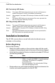
5 FINAL.Not for distribution. 802.11a Activity LED Amber Booting The amber LED flashes three times per second until firmware is loaded. During boot, no 802.11a mobiles can associate. After adoption, the amber LED is steady or flashes with 802.11a radio traffic. The amber LED flashes once per second if an error prevents the 802.11a radio from operating normally. Normal Error 802.11b/g Activity LED Green Booting Normal Error The green LED flashes three times per second until firmware is loaded.
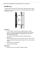
6 AP 300 Quick Reference Guide FINAL.Not for distribution. Wall Mounting In this procedure, hang the AP 300 Access Port along its width or length using the slots on the bottom of the unit. The following illustration shows a lengthwise mount.
7 FINAL.Not for distribution. RJ-45 RJ-45 2. Using the arrows on the edge of the case as guides, move the edge to the midline of the mounting area and mark points on the midline for the screws. 3. At each point, screw in the self-tapping screws and stop where the threads meet the shank or shoulder of the screw. 4. If required, install and attach a security cable to the unit’s lock port. Lock Port 5. Place the large corner of each of the case’s mount slots over the screw heads. 6.
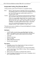
8 AP 300 Quick Reference Guide FINAL.Not for distribution. Suspended Ceiling Tile (Plenum) Mount In this procedure, place the AP 300 above a suspended ceiling. Note: Notes or warnings about suspended ceiling mounts apply to all installations where the unit is placed on suspended ceiling tile. The AP 300 case has a safety cable tie point for a standard safety cable. Caution: Symbol does not recommend mounting the AP 300 directly to any suspended ceiling tile with a thickness less than 1.27cm (0.5in.
9 FINAL.Not for distribution. Safety Cable Light Pipe Ceiling Tile Decal Badge 5. Snap the clips of the light pipe into the bottom of the case. 6. Fit the light pipe into hole in the tile from its unfinished side. 7. Place the decal on the back of the badge and snap the badge onto the light pipe from the finished side of the tile. 8. Bring the tile into the ceiling space, and attach any safety cable to the safety cable tie point or security cable to the unit’s lock port. 9.
10 AP 300 Quick Reference Guide FINAL.Not for distribution. Customer Support Symbol Technologies provides its customers with prompt and accurate customer support. Use the Symbol Support Center as the primary contact for any technical problem, question or support issue involving Symbol products. If the Symbol Customer Support specialists cannot solve a problem, access to all technical disciplines within Symbol becomes available for further assistance and support.
FINAL.Not for distribution. Web Support Sites MySymbolCare http://www.symbol.com/services/msc Symbol Services Homepage http://symbol.com/services Symbol Software Updates http://symbol.com/services/downloads Symbol Developer Program http://software.symbol.com/devzone Symbol Knowledge Base http://kb.symbol.com/register.asp Additional Information Obtain additional information by contacting Symbol at: • 1-800-722-6234, inside North America • +1-631-738-5200, in/outside North America • http://www.symbol.
12 AP 300 Quick Reference Guide FINAL.Not for distribution. Legal Information Regulatory All Symbol devices are designed to be compliant with rules and regulations in locations they are sold and will be labeled as required. Any changes or modifications to Symbol Technologies equipment, not expressly approved by Symbol Technologies, could void the user's authority to operate the equipment. Use only the supplied or an approved replacement antenna.
13 FINAL.Not for distribution. FCC RF Exposure Guidelines Safety Information Caution: The device complies with internationally recognized standards covering Specific Absorption Rate (SAR) related to human exposure to electromagnetic fields from radio devices. It is advisable to use the device only in the normal operating position. Remote and Standalone Antenna Configurations.
14 AP 300 Quick Reference Guide FINAL.Not for distribution. Radio Transmitters This device complies with RSS 210 of Industry & Science Canada. Operation is subject to the following two conditions: (1) this device may not cause harmful interference and (2) this device must accept any interference received, including interference that may cause undesired operation. Label Marking: The Term "IC:" before the radio certification only signifies that Industry Canada technical specifications were met.