SYMEO LPR® Product Documentation Product: LPR-1D
® SYMEO LPR LPR-1D Product Documentation CONTENT 1 OVERVIEW ...................................................................................................... 7 1.1 Safety Instructions ................................................................................................... 8 1.2 Installation ................................................................................................................ 8 1.3 Repairs ....................................................................
® SYMEO LPR LPR-1D Product Documentation 3.3.1 Example Connector Box ........................................................................................... 26 3.4 LPR® Antenna Types .............................................................................................. 28 3.4.1 Adapter for different LPR® Antennas......................................................................... 29 4 INSTALLATION ..........................................................................................
® SYMEO LPR LPR-1D Product Documentation 6.5.4 Step 4 – Restart........................................................................................................ 64 6.6 System Log ............................................................................................................. 65 7 PROTOCOL DESCRIPTION BINARY XP (1D MESSAGES) ........................ 67 7.1 7.1.1 7.1.2 7.1.3 7.1.4 General Description....................................................................................
® SYMEO LPR LPR-1D Product Documentation 9 APPENDIX A: AGENCY CERTIFICATIONS ................................................. 85 United States (FCC) and Canada (Industry Canada) ....................................................... 85 United States (FCC) ........................................................................................................... 85 Canada (Industry Canada) .................................................................................................
® SYMEO LPR LPR-1D Product Documentation The documentation for the LPR® System is published by: SYMEO GmbH Prof.-Messerschmitt-Str. 3 D-85579 Neubiberg www.symeo.com If you have any questions or suggestions, please contact: Email: info@symeo.com phone: +49 89 660 7796 0 Copyright Symeo GmbH 2007 All rights reserved HISTORY Overview 3.17 14.12.2008 New Layout 3.18 11.02.2009 Added all single documents to one master document 3.19 30.03.2009 Added notes for FCC/IC conformity 3.20 13.07.
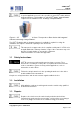
® SYMEO LPR LPR-1D Product Documentation 1 Overview SYMEO Industrial LPR® is a system for contactless, real-time determination of distances and positions. LPR® 1D is a distance measurement system which is particularly well suited for use in very harsh, industrial environments, in which other systems such as mechanical rotary encoders or lasers cannot function for long periods.
® SYMEO LPR LPR-1D Product Documentation In special application cases it is also possible to get a LPR® station with an integrated antenna. This hardware is called LPR® design ”Integral Station” compared to the hardware LPR® 1D design “Compact Station”. Figure 2 – LPR® Hardware – Special Case: Transponder or Base Station with integrated antenna in the design “Integral Station” The LPR® 1D Station with an integrated antenna is available in a plastic housing.
® SYMEO LPR LPR-1D Product Documentation 1.4 Transport and Storage Use the original packaging or other suitable packaging for returns and whenever the system is to be transported. This ensures protection from crushing, impacts, moisture and electrostatic discharge. During setup and before operation, refer to the instructions for environmental conditions included in the operating instructions for the device. Route the wires in such a way that they do not cause a hazard and are not damaged.
® SYMEO LPR LPR-1D Product Documentation In the case of high outside temperatures and intense, direct solar radiation or other radiant heat, it may be necessary to provide a sun or heat shield. 1.7 System Extensions and Accessories Data links to peripheral devices must be provided with adequate shielding. For LAN cabling, the requirements in accordance with EN 50173 and EN 50174-1/2 apply.
® SYMEO LPR LPR-1D Product Documentation 2 2.1 System Description System architecture SYMEO Industrial LPR® is a system for contactless, real-time determination of distances and positions. LPR® 1D is a distance measurement system which is particularly well suited for use in very harsh, industrial environments, in which other systems such as mechanical rotary encoders or lasers cannot function for long periods. All devices have a unique identifier, via which they are actuated.
® SYMEO LPR LPR-1D Product Documentation 2.3 System Configuration The LPR® 1D system consists of two, three, four or five LPR® units. Each of these units can be configured either as a transponder or as a base station. A system consists of exactly one LPR® unit configured as a transponder and between one and four LPR® units configured as base stations. For pure 1D distance measurement two units are required and are arranged as shown in Figure 3. The distance information is available at both stations.
® SYMEO LPR LPR-1D Product Documentation Station 1 Transponder Station 2 Base Station Station 3 Base Station Station 4 Base Station Station 5 Base Station The hardware of a transponder and base station looks like the same. The only difference is the configuration software. The transponder organizes the measurements. It allocates time slots to the base stations to identify when these stations are allowed to start with a measurement. 2.4.
® SYMEO LPR LPR-1D Product Documentation System Number 1 System Number 2 Group-ID: 1 FSK-Channel: 8 Group-ID: 2 FSK-Channel: 9 Station 1 Station 2 Station 1 Station-ID: 1 Station-ID: 2 Station-ID: 1 System Number 3 Station 2 Station-ID: 2 Station 4 Station 3 Station-ID: 3 Station-ID: 4 System Number 4 Group-ID: 3 FSK-Channel: 10 Group-ID: 4 FSK-Channel: 11 Station 1 Station 2 Station 1 Station-ID: 1 Station-ID: 2 Station-ID: 1 Station 2 Station-ID: 2 Station 3 Station-ID: 3 F
® SYMEO LPR LPR-1D Product Documentation Besides distance measurement, the system's communication can be used for transmitting user data in the intervals between measurements. Transmission is asynchronous, i.e. the data is requested and transmitted when the measurement has been completed. To transmit data over the system, first a send data request is sent by the LPR® unit to the user. Then the user data is received and transmitted to the second LPR® station.
® SYMEO LPR LPR-1D Product Documentation 2.6.2 Positioning of Crane Crab (LPR® 1DP2) In order to determine positions in two dimensions (x-y coordinates), three LPR® units can be arranged in an L-shape (see Figure 7). In this case, the unit that is configured as the transponder (station 1) is equipped with 2 antennas. This unit measures against the first base station (station 2) with the first antenna, and against the second base station (station 3) with the other antenna, for example.
® SYMEO LPR LPR-1D Product Documentation 2.6.3 Positioning of 2 Cranes on two Runways (LPR® 1DP) The Y-shaped arrangement can be used to determine the position of two cranes on different crane runways, for example. In the arrangement shown in Figure 8, the transponder unit (station 1) is equipped with two antennas. One base station (station 2 and station 3) is installed on each of the two cranes.
® SYMEO LPR LPR-1D Product Documentation 3 Hardware All corresponding installation, repair and servicing work must be carried out by qualified and trained technicians. Using beside the LPR® station with design “Compact Station” a LPR® station with design “Integral Station” a separate document with hardware and installation description is provided. 3.
® SYMEO LPR LPR-1D Product Documentation 1 60 1 2 91 3 26 4 0 5 6 Figure 9 LPR® Station (with network interface, dry contacts and 2 antenna interfaces) Description of Interfaces Nr. 1 Pressure equalization membrane. The membrane prevents forming of condensation water inside the Compact Station. The pressure equalization membrane must not be changed or covered! Nr. 2 Network (optional). The standard industrial Ethernet port of the station is designed as a Harting type push pull connector. Nr.
® SYMEO LPR LPR-1D Product Documentation 3.1.
® SYMEO LPR LPR-1D Product Documentation 3.1.2 PIN-Assignment of Lumberg Typ 0233 14 (Relays) Overview 3 4 2 12 5 13 6 1 11 10 14 Pin Name Function 1 R1P The function of the relay 1 to 7 can be 2 R1N individually programmed with the LPR® 1D 3 R2P 4 R2N 5 R3P 6 R3N 7 R4P 8 R4N 9 R5P 10 R5N 11 R6P 12 R6N 13 R7P 14 R7N Wizard.
® SYMEO LPR LPR-1D Product Documentation Figure 10 Cable for power supply with integrated interface PIN-Assignment of Cable Lumberg Connector 0223 08 Plug Lumberg 0223 08 Cable 8-wire AWG24 UL/CSA; cladding diameter = 6.
® SYMEO LPR LPR-1D Product Documentation system via the RXD-wire. Then measurements can fail. You have to ground the RXD-wires (PIN 3 and PIN 5) with PIN 7 and 8. 3.2.2 Assembled Cable for relays Cables are delivered with a cable length of 5m and can be cut to the required length.
® SYMEO LPR LPR-1D Product Documentation PIN-Assignment of cable Lumberg Stecker 0223 14 Plug Lumberg 0223 14 Cable 16-wire (14 wires are only used!) AWG24 UL/CSA; cladding diameter = 6.
® SYMEO LPR LPR-1D Product Documentation 3.3 LPR® Connection Box The connection box is configured with 14 clamps. Therefore the connector box can be used either for power supply or for relays. Figure 12 Connection Box Connection Box Size (LxWxH) 125mm x 80mm x 57mm (without cable bushing) Position mounting holes 4 x diameter 4.3mm; 52 x 113mm Clamps Wago 870-911 for cable diameter 0.
® SYMEO LPR LPR-1D Product Documentation 3.3.1 Example Connector Box Connection of a 8-pin cable 1: Power consumption (by customer) 2: Serial Interface (by customer) ® 3: From LPR 1 2 3 Figure 13 Example for wiring connector box with 8 pins In this example the power supply is at pin1 and 2. The serial interface is at pin 5 to 10 and the shielding at pin 14. The shielding has to be allocated. For safety of clamping use appropriate wires end sleeves according to AWG24.
® SYMEO LPR LPR-1D Product Documentation Connection of a 14 pin cable. 1: By customer 2: Sealing ring 3: Sealing cover ® 4: From LPR 2 1 3 4 Figure 14 example for wiring of connector box with 14 pins The dry contacts have to be connected to the clamps 1-14. The cable gland in the middle has to be protected with a sealing cap to keep protection category IP65.
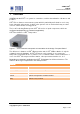
® SYMEO LPR LPR-1D Product Documentation LPR® Antenna Types 3.4 There are different antennas that can be installed depending on the required directional characteristic. Figure 15 shows the typical LPR® antennas, which are applied in an LPR® System.
® SYMEO LPR LPR-1D Product Documentation -3 dB 10 dBi Sector Antenna (*) -3 dB d Antenna Connector Type N A = 280mm B = 125mm d = 150mm A B 30° 60° (optional) vertical 160° 0 dB 0 dB -3 dB -3 dB horizontal -3 dB 14 dBi Sector Antenna (*) d Antenna Connector Type N A A = 510mm B = 90mm d = 80mm 4° vertical -3 dB 0 dB -3 dB 90° 0 dB B -3 dB horizontal Figure 15: Example of directional characteristic of typical LPR® antennas (*) These antennas are NOT approved to be in compliance with
® SYMEO LPR LPR-1D Product Documentation 6 dBi and 10 dBi Omnidirectional Antenna d applicable for wall and pole mounting A = 228mm B = 38mm d = 50mm A B 23 dBi Planar Antenna B Part 1: mounting at antenna B A = 115mm B = 115mm A Part 2: applicable for wall and pole mounting A = 80mm B = 110mm d = 70mm applicable for pole diameter of 25mm-76mm A 12 dBi Planar Antenna B applicable for wall mounting A = 50mm B = 44mm d = 22mm A 10 dBi Sector Antenna d applicable for wall and pole mounting A A =
® SYMEO LPR LPR-1D Product Documentation 4 4.1 4.1.1 Installation Installation of LPR® Station Design Compact Station Important Instructions for Installation During Installation, the Compact Station has to be opened. Therefore it is important to avoid ingress of moisture, dust or any particles into the housing during the installation process.
® SYMEO LPR LPR-1D Product Documentation Transponder Base Station Base Station Base Station Base Station Station 1 Station 2 Station 3 Station 4 Station 5 Measured Antenna Antenna Distance 1 x x x Port 1 Port 1 x x Measured Antenna Distance 2 Port 2 (optional) Measured Port 1 Antenna Distance 3 Antenna x x Port 3 (optional) Measured x Port 1 Antenna Distance 4 (optional) Antenna x Antenna x x Port 4 x Port 1 When installing the cable, ensure that electrostatic cha
® SYMEO LPR LPR-1D Product Documentation For installation of the Planar Antennas, it is important to keep the same orientation of polarization for corresponding antennas (see Figure 17). Figure 17: Backside of 23 dBi Planar Antenna Install the antenna fixture according to the accompanying operating instructions. Secure the antenna in the fixture. Connect the antenna to the antenna cable. 4.2.3 Fresnel zone The area for radio transmission between two antennas is called Fresnel zone.
® SYMEO LPR LPR-1D Product Documentation Figure 18 Calculation and figure of Fresnel zone 4.2.4 Installation of Planar Antennas Each antenna type has its own opening angle. To communicate with the opposite antenna the relative antennas has to be located in the opening angles of the opposite antennas. Antennas have to be mounted without any offset (no difference in height and no offset sideways). Make sure that the opening angle is symmetric to the relative direction of motion (compare picture 1 vs.
® SYMEO LPR LPR-1D Product Documentation Data link has been established serially or via TCP/IP. Once these prerequisites have been fulfilled you can connect the station either serially to a PC or as an option (TCP/IP option) to the network and commission the LPR® 1D system. How to do this is explained in the following chapter. 5.1.1 General Commissioning is carried out via the serial port or the TCP/IP port depending on the LPR® station model you have.
® SYMEO LPR LPR-1D Product Documentation Possible Connection to the LPR® Station via PC RS232 TCP/IP Wireless-Access (via another LPR® Station) Parameterization YES YES YES (ASCII-Data) (ASCII-Port) (ASCII-Port) (ASCII-Port) Distance Data YES YES NO (Binary Data) (Binary Port) (Binary Port) In one LPR® system all distance data (binary data/ protocol) is available at each station.
® SYMEO LPR LPR-1D Product Documentation If you firewall settings are too restrictive, you may not get access to the LPR® station. In this case deactivate temporarely the firewall under the tab „Advanced“ in the window LAN Properties. The LPR® Station should be available via your PC now. You can check the connection with a „ping” to the LPR® station: Open the Command-Window: Windows Start Button Choose Run Enter cmd and click OK Enter in the cmd.exe window: ping 192.168.1.
® SYMEO LPR LPR-1D Product Documentation Figure 23 – Lumberg-Interface for Serial Interface Figure 24 – Lumberg-Connector Cable for Serial Interface Pin Function 1 UBB (+) 2 UBB (-) 3 LPR® data port RXD 4 LPR® data port TXD 5 Network diagnostic port RXD 6 Network diagnostic port TXD 7 GND-RS232 8 GND RS232 Pin / Color Function 1-ws UBB (+) 2-bn UBB (-) 3-gn LPR® Dataport TXD 4-ge LPR® Dataport RXD 5-gr Network diagnostic port RXD 6-rs Network diagnostic port TXD 7-bl GND
® SYMEO LPR LPR-1D Product Documentation Figure 26 – Internal Data Interfaces ® Figure 25 Internal view of LPR Station Internal Data Interfaces S4 Configuration Port/ ASCII Port S3 A9 serial S2 Binary Port (Protocol XP) S1 ARM9 serial Connect one side of RS232 cable of a cable length of 2 m with your PC and the other side with the LPR® station (ASCII Port S4). Check the right port of your COM-Port in the device manager of your computer. 5.4 5.4.
® SYMEO LPR LPR-1D Product Documentation Figure 28 – Setup 1 Figure 30 – Setup 3 Figure 29 – Setup 2 After finishing the installation process, you can open the LPR®-1D Wizard via the Windows menu. 5.4.2 Utilization of LPR® 1D Wizard The commissioning of the LPR® 1D system with the LPR®-1D Wizard proceeds the following: Selection of the desired application Settings of parameters for selected application General setting of LPR® 1D System (ID, Antenna parameters, etc.
® SYMEO LPR LPR-1D Product Documentation Start the LPR® 1D Wizard. The following window appears: The construction of the menu looks like the following: Menu ‚File„: open and save configuration files. Menu ‚Application„: Selection of application and ® settings for LPR -Systems (IDs, allocation of relays,…) Menu ‚Connection„: Connection to LPR system. ® You find many Info buttons. These info buttons explain in more detail the functionality of an action.
® SYMEO LPR LPR-1D Product Documentation The first possible application is shown. You can see other application with the buttons ‚Next application„ or previous application„. Or you can open a known application via the selection list ‚Direct link to your application„. Not till then you have pressed the button ‚Choose this application„ the applicationi selected. The button ‚Info about this application„ contains a short description of the application.
® SYMEO LPR LPR-1D Product Documentation The ‚Common Settings„ include settings of LPR Systems. You have to make these settings. ® ® Group ID: Clear ID of the LPR system. All ® station in one LPR system have the same group ID. ® SCIB-data rate: Transmission rate of the LPR system. Per default this value iss et to 115200 baud. If you change the baud rate, you should also adjust the measurement rate of the system.
® SYMEO LPR LPR-1D Product Documentation Antenna Port 1 Antenna Port 2 Figure 38 – Antenna ports of LPR Station ® Optional: Usage of Relays ® If realys are used at one or more LPR stations you can allocate functionalities to each relay depending on the selected application. If the relay selection is skipped no relays are switch ® at the LPR station You can choose between default settings, customer settings and no relay.
® SYMEO LPR LPR-1D Product Documentation TCP/IP Connection: To open the TCP/IP connection you have to enter the IP-address and the port number. The configuration port is 3045 per default. It can be ® changed in the web interface of the LPR station (see chapter 6). RS232 Connection: T open the serial connection select the right COM port of your computer. Figure 41 – TCP/IP Connection to LPR station ® You can control the COM port number in the device manager of your computer.
® SYMEO LPR LPR-1D Product Documentation Press the button ‚Start‟. Enter the desired file name. Symeo recommends entering the station number, the group number or the serial number to distinguish later the configuration files of all stations. The serial number is labeled ® outside the LPR station. Upload Configuration Pressing the button ‚Upload„ the application can ® be uploaded to each LPR station. If settings were changed or a new application is chosen, all stations must be uploaded.
® SYMEO LPR LPR-1D Product Documentation ® At each LPR station an upload must be done. ® You can either connect the LPR station direct to your computer via TCP/IP or serial interface. Or you have the possibility to get wireless access via station 1 (coordinator) via the frequency channel to the other stations But to get wireless to other stations you have to know some parameters of the opposite station. These are the previous group ID, the previous station number and the antenna port at this station.
® SYMEO LPR LPR-1D Product Documentation the antennas should have a real distance to each other of 5 to 20 m. Display of Distance Data Click the button ‚Distance Data„ and distance value(s) is/are shown.
® SYMEO LPR LPR-1D Product Documentation 6 Web Server The network settings for a LPR® station with TCP/IP interface are described in this chapter. Therefore it is necessary to open a TCP/IP connection between your computer and the LPR® station. 6.1 Open Web Server Open your web browser. In the address bar of the web browser enter the IP-address of the LPR® station: http://192.168.1.99. Press Enter. The IP-address of the LPR® station is 192.168.1.
® SYMEO LPR LPR-1D Product Documentation 6.2 Settings With this function you can define the network settings on your LPR® station and the network access settings and reboot the system. Click "Settings" in the navigation bar. If you have not yet provided authentication information you will be prompted to do so now (see chapter 6.1). The Settings page for the LPR® station's Web server is displayed.
® SYMEO LPR LPR-1D Product Documentation 6.2.1 „LAN“ area MACAddress Unique hardware address of the LPR® station on the LAN (Ethernet ID) (not editable) Current Mode Shows the current mode: "Static IP-Address" or "DHCP Active". In "DHCP Active" mode, the LPR® station receives a dynamic or reserved IP address from the DHCP server. You can also ask your administrator or the SYMEO technical department about this.
® SYMEO LPR LPR-1D Product Documentation In "DHCP Active" mode this address is assigned by the server and cannot be edited. Syslog IP address of the Syslog server (default: 0.0.0.0, i.e. this service has been disabled). The Syslog server is a server on the network to which it is planned to have system messages (system log) transmitted. Transmission is packet-based (UDP) and unencrypted. NTP IP address of the NTP server (default: 0.0.0.0, i.e. this service has been disabled).
® SYMEO LPR LPR-1D Product Documentation Disabled The port is disabled and not reachable via TCP/IP. TCP – Listening on Data Port The LPR® station is waiting for incoming connection on the “Data Port”. If the connection is opened successful you can open the parameterization port. TCP – Connection to Data Port using Reserve Port The LPR® station establishes the connection to the entered server address. Setting “Random” means both communication partners arrange the reverse channel autonomously.
® SYMEO LPR LPR-1D Product Documentation activated „Byte Stuffing“ (no fixed protocol length). TCP – Fixed Frame – Listening on Data Port The LPR® station is waiting for incoming connection on the “Data Port”. If the connection is opened successful you can open the binary port. „Fixed Frame“ means deactivated „Byte Stuffing“ (fixed protocol length). TCP – Fixed Frame – Connecting to Data Port The LPR® station establishes the connection to the entered server IP-address.
® SYMEO LPR LPR-1D Product Documentation Password Extended system access („Remote Access“) enables console access via Telnet, SSH (Secure SHell), SCP (Secure CoPy) and via the serial port. This enables extended system information to be retrieved and troubleshooting to be carried out. We recommend that you disable all functions that are not required, see section "Settings". In extended system access, the user "SYMEO" has 'ROOT' privileges, i.e., full access to the system.
® SYMEO LPR LPR-1D Product Documentation 6.2.7 Accept settings / System Reboot As described in chapter 6.2 it is necessary to transmit the changes to the LPR® station and afterwards reboot the station. Press button „Upload changes“ to load the changes. Scroll down to the end of the page and press „Reboot System“ to reboot the LPR® station.
® SYMEO LPR LPR-1D Product Documentation 6.3 System Status With this function, you can display the current system status. Click "Status" in the navigation bar. If you have not yet provided authentication information, you will be prompted to do so now (see section "Starting and using the Web server"). The Status page for the LPR® station's Web server is displayed.
® SYMEO LPR LPR-1D Product Documentation 0x0 Rev. A 0x1 Rev. B 0x2 Rev. C 0x3 Rev. D0 0x4 Rev. D1 0x5 Rev. E0 0x6 Rev. E1 0x7 Rev. E2 6.4 Diagnostics Connections: State of the active and inactive connection to the LPR® station Partitions: Size and name of available partition of non-volatile memory. The size of receive buffer (Recv-Q) and send buffer (Send-Q) should be zero if possible. A long lasting value grater zero means problems when receiving or sending data.
® SYMEO LPR LPR-1D Product Documentation Local-Address: LPR® Interface address (0.0.0.0 – listening to all interfaces) Foreign Address: IP-address of opposite station State: Status of connection Example 2: - successful established connection Proto RecvQ SendQ Local-Address Foreign Address State tcp 0 1 192.168.1.99:3045 192.168.1.1:1333 ESTABLISHED Of Connection Type „TCP - Listening on Data Port“ (ttyAM1) is enabled this table shows further connection information.
® SYMEO LPR LPR-1D Product Documentation The page Firmware Update of the WebServers of the LPR® station is displayed. A firmware update is performed in several steps: Step 1: File system Step 2: Linux-Kernel Step 3: Optional (2D Application) Step 4: Restart Step 3 is exclusively for an update for 2D application. Otherwise this part can be skipped. 6.5.1 Step 1 – File system It is possible to make a copy of the actual firmware by downloading the firmware from the LPR® station.
® SYMEO LPR LPR-1D Product Documentation Click the "Upload" button in the "Step 1 – flash ramdisk.gz" area. The file has been transferred. Click the "back: Firmware Update" link. Click the "Execute" button in the "Step 1 – flash ramdisk.gz" area to transfer the file to the non-volatile memory.
® SYMEO LPR LPR-1D Product Documentation Transfer progress is displayed in a message window. You will know when this operation is complete because a message: "... done, file ramdisk.gz removed" will be output and a link "back: Firmware Update" is provided Click the "back: Firmware Update" link. 6.5.2 Step 2 – Linux Kernel It is possible to make a copy of the actual firmware by downloading the firmware from the LPR® station. Click the button „Backup zImage “.
® SYMEO LPR LPR-1D Product Documentation Click the "Upload" button in the "Step 2 – flash zImage" area. The file has been transferred. Click the "back: Firmware Update" link. Click the "Execute" button in the "Step 2 – flash zImage" area to transfer the file to the non-volatile memory.
® SYMEO LPR LPR-1D Product Documentation Transfer progress is displayed in a message window. You will know when this operation is complete because a message: "... done, file zImage removed" will be output and a link "back: Firmware Update" is provided Click the "back: Firmware Update" link. 6.5.3 Step 3 – Optional: Userspace This step is exclusively for 2D-applications necessary and is executed the same way as described before. 6.5.
® SYMEO LPR LPR-1D Product Documentation To do this, click the "Execute" button in the "Step 3 – Restart" button. The system will be restarted. If the new firmware contains additional configuration files the settings you made are set to factory settings. This would be also applied for the IP-address which is et the tot he default value 192.168.1.99. Symeo recommends restoring the factory settings after a firmware update and reenter the customer settings. 6.
® SYMEO LPR LPR-1D Product Documentation Click "System Log" in the navigation bar. If you have not yet provided authentication information, you will be prompted to do so now (see chapter 6.1). The last 10 system messages will be displayed. The message window is updated about once per second.
® SYMEO LPR LPR-1D Product Documentation 7 Protocol Description Binary XP (1D messages) 7.1 General Description This protocol describes the interface between a LPR®-B station and the user. The binary protocol XP protocol provides information in high density. Its structure ensures a simple implementation. The transfer is done in single data frames. The interface for the binary protocol XP can either be a serial (RS232) interface or a TCP/IP or UDP interface.
® SYMEO LPR LPR-1D Product Documentation The TYPE-field is following the DATA-field. The DATA field contains the real data of the packet of the type TYPE. The CRC-field contains a check sum. The check sum is applied to all previous data fields except the START data field. All multi byte integers (e.g. CRC field) are encoded in Network-Byte-Order (Big Endian). All signed integers are encoded in two's complement representation. 7.1.
® SYMEO LPR LPR-1D Product Documentation 7.2 Data Types The second byte in each data packet specifies the data type. Type 0x00 – Distance Data 7.2.1 Direction: LPR®-B → User Content Length Data type Value START 1 unsigned integer 0x7E TYPE 1 unsigned integer 0x00 Source (LPR address) 2 see chapter 7.4.1 0x#### 1 2 see chapter 7.4.
® SYMEO LPR LPR-1D Product Documentation 7E hex START byte 02 hex TYPE (02; Send Request) C1 81 7F hex CRC END byte hex Distance data: 7E 00 08 03 08 02 11 00 00 10 62 00 00 00 7A E6 00 00 AF C4 7F 7E hex START byte 00 hex TYPE (00: Distance Data) 08 03 hex = 00001|0000000001|1 bin 08 02 hex = 00001|0000000001|0 bin 11 = 0001|0001 hex hex = 4194 00 00 00 7A hex = 122 hex 00 hex 00 hex AF C4 7F = 230 Destination LPR®-B address: SID: 1; GID: 1; BBt: 0 (transponder) Ant
® SYMEO LPR LPR-1D Product Documentation Total length without byte stuffing: 15 byte 7.2.3 Type 0x02 – Send Request Direction: LPR®-B → User Content Length Data type Value START 1 unsigned integer 0x7E TYPE 1 unsigned integer 0x02 CRC 2 unsigned integer 0xC181 END 1 unsigned integer 0x7F Total length without byte stuffing: 5 byte This packet is sent from the LPR®-B station continuously. It informs the user that the LPR®-B station is able to receive data from the user.
® SYMEO LPR LPR-1D Product Documentation 7.3 TCP/IP option: Fixed Frame Protocol If the LPR® station has a TCP/IP interface two options are available for the protocol. Either you use the protocol as it is sent from the serial interface (with different data type lengths, byte stuffing) or you use a fixed frame protocol. In the first case the data symbols 0x7e und 0x7f (which are reserved for the START and END field) are replaced (see chapter 7.1.3). Byte stuffing causes a different protocol length.
® SYMEO LPR LPR-1D Product Documentation If data is sent to the LPR® unit the data has to be packed in a fixed data length (i.e. 15 bytes as for TCP fixed frame option). This data packet is sent as UDP packet to the LPR® unit. The port number of the receiver is the same as for the PC. In general bidirectional data communication is not recommended for UDP due to loosing singular data packets. 7.4 Remarks 7.4.
® SYMEO LPR LPR-1D Product Documentation 8 Trouble Shooting This chapter will assist you for troubleshooting. For debugging circumstances it might be helpful to install a terminal program to analyze the system. 8.1 Programs 8.1.1 Terminal Program A Terminal program is useful for analyzing the system. The recommended terminal program is RealTerm. It is Open Source Software and can be downloaded from the webpage http://sourceforge.net/projects/realterm. Install the program on your PC. 8.1.
® SYMEO LPR LPR-1D Product Documentation If you want to use a longer serial cable you have to reduce the baud rate of the LPR-B station. Ask the Symeo Service for detailed information. Typical values for the data rate for different length of the serial cables are: Max. baud Max. Length of RS232 rate cable 9.600 152 m 19.200 15 m 57.600 5m 115.200 <2 m 8.
® SYMEO LPR LPR-1D Product Documentation In two tabs you have to change the settings: Tab Display: - Choose Display As Ansi - Extend the Rows from 16 to 30 Tab Port: - Change the Baud to 115.200 - Choose the right COM port - Click On Open Depending if you are connected to a transponder or a base station characters may appear in the window. If you are connected to a transponder a lot of “t” characters appear.
® SYMEO LPR LPR-1D Product Documentation If you press button “1” (configuration menu) and button “6” (setup) then you can get more detail about the system. Click maybe on freeze to enable the scroll bar and scroll up to setup menu. Note the point f……..fsk channel. With the character “x” you return to the main menu.
® SYMEO LPR LPR-1D Product Documentation 8.5.1 LAN Settings of your PC First you need to disconnect your PC from your network to avoid trouble when changing the IP address of your computer. Now you connect the LPR-B station via an Ethernet cable with your PC. If you are not in the same net as the LPR-B station you have to change temporary the network settings of your PC. Both IP-address must be in the same network, i.e. the first three fields of the IP-address must match.
® SYMEO LPR LPR-1D Product Documentation You should get a reply from the LPR-B station with the fixed IP-address 192.168.1.99 If the connection failed probably your firewall settings of your PC are set to restrictive or the IP-address of the LPR-B station is probably not 192.168.1.99. Please check the settings. Compare also the hint in chapter 8.5.1. If you have changed the IP address without bearing in mind the IP address the IP-address could be detected with the program NetworkScanner. 8.5.
® SYMEO LPR LPR-1D Product Documentation In both cases you can click inside the window and press the button 3. If nothing appears than there is something wrong with the connection between the LPR-B station and your computer or the station has no power. Normally it shows you some system information: In the upper line is written the System Address: The system address indicates if the station is a transponder or a base station and which group ID the station has.
® SYMEO LPR LPR-1D Product Documentation If you do not get access to the LPR-B station check if the port is open. The port for the parameterization is 3045 per default. But it might be possible that you have changed it or did not open it (see chapter 8.5.5). 8.5.5 Web Interface If you can “ping” the IP-address of the LPR-B station but do not get data (either via the parameterization port or the binary port or both ports) you have to check the settings on the web page of the LPR-B station.
® SYMEO LPR LPR-1D Product Documentation Scroll down to the section: Serial-to-Ethernet: Here you enter the connection type for the parameterization port (ttyAM1) and the binary port (ttyAM2). Both ports should be not disabled. Choose the right connection type and enter the data port. The data port is per default 3045 for the parameterization port and 3046 for the binary port. If you have made changes click on “Upload changes” and then on “Reboot system”.
® SYMEO LPR LPR-1D Product Documentation measurement 2 (optional) 1 Antenna an Port 2 1 x Antenna at Port 1 3) If you use planar antennas the orientation of the antenna must be correct. A small label on the backside of the antenna indicates the horizontal and vertical alignment. 4) For a distance measurement always two stations are involved. It has to be a transponder unit and a base station unit. Make sure that never two base stations or two transponders a measuring with each other.
® SYMEO LPR LPR-1D Product Documentation If you use LPR-B stations with and without TCP/IP jumpers are set differently. To make the parameterization via serial connection jumpers has to be changed (only the both lower pictures are set for configuration the LPR-B station via the serial cable). 4) Overwrite the configuration with the program LPR 1D wizard for all stations.
® SYMEO LPR LPR-1D Product Documentation 9 Appendix A: Agency certifications United States (FCC) and Canada (Industry Canada) Radiofrequency radiation exposure Information: This equipment complies with FCC/IC radiation exposure limits set forth for an uncontrolled environment. This equipment should be installed and operated with minimum distance of 20 cm between the radiator and your body. This transmitter must not be co-located or operating in conjunction with any other antenna or transmitter.
® SYMEO LPR LPR-1D Product Documentation However, there is no guarantee that interference will not occur in a particular installation. If this equipment does cause harmful interference to radio or television reception, which can be determined by turning the equipment off and on, the user is encouraged to try to correct the interference by one or more of the following measures: Reorient or relocate the receiving antenna. Increase the separation between the equipment and receiver.
® SYMEO LPR LPR-1D Product Documentation 23 dBi Planar Antenna B Antenna Connector Type N 9° A = 305mm A B = 305mm vertical d = 25mm -3 dB 0 dB -3 dB 9° horizontal -3 dB 0 dB -3 dB Figure 47: LPR® 1D antenna Appendix A: Agency certifications Copyright © Symeo GmbH 2010 Page 87 of 87