XLi IEEE 1588 Clock User Guide 997-01510-03, Rev.
Notices Symmetricom, Inc. Timing Test & Measurement 3750 Westwind Blvd. Santa Rosa, CA 95403-1053 http://www.symmetricom.com Copyright © 2006, Symmetricom, Inc. All rights reserved. Printed in U.S.A. All product names, service marks, trademarks, and registered trademarks used in this document are the property of their respective owners. The manual’s contents do not apply to previously released versions of XLi hardware or software.
S S S S S S S S S S S S S S S S S S S S S S S S S S S S S S S S S S S S S S S S Table of Contents 1: Overview and Features . . . . . . . . . . . . . . . . . . . . . . . . . . . . . . . . 1 Overview . . . . . . . . . . . . . . . . . . . . . . . . . . . . . . . . . . . . . . . . . . . . . . . 1 Description . . . . . . . . . . . . . . . . . . . . . . . . . . . . . . . . . . . . . . . . . . . . 1 Standard Configuration . . . . . . . . . . . . . . . . . . . . . . . . . . .
S 1 S S S S S S S S S S S S S S S S S S S S S S S S S S Configuring the IEEE 1588 Card(s) . . . . . . . . . . . . . . . . . . . . . . . . . PTP Master . . . . . . . . . . . . . . . . . . . . . . . . . . . . . . . . . . . . . . . . . PTP Slave . . . . . . . . . . . . . . . . . . . . . . . . . . . . . . . . . . . . . . . . . . Rack Mounting the XLi . . . . . . . . . . . . . . . . . . . . . . . . . . . . . . . . . . .
S S S S S S S S S S S S S S S S S S S S S S S S S S S S S S S S S S S S S S S S F51 – GPS Antenna Cable Delay . . . . . . . . . . . . . . . . . . . . . . . . . . . 55 F52 – Distribution Cable Delay . . . . . . . . . . . . . . . . . . . . . . . . . . . . . 57 F53 – GPS Operation Mode . . . . . . . . . . . . . . . . . . . . . . . . . . . . . . . . 58 F60 – GPS Receiver Satellite List . . . . . . . . . . . . . . . . . . . . . . . . . . .
S S S S S S S S S S S S S S S S S S S S S S S S S S S S S S S S S S S S S S S S PTP Sync message interval . . . . . . . . . . . . . . . . . . . . . . . . . . . . 120 PTP burst mode enabled/disabled . . . . . . . . . . . . . . . . . . . . . . . 121 PTP network port enabled/disabled . . . . . . . . . . . . . . . . . . . . . . 121 PTP subdomain same . . . . . . . . . . . . . . . . . . . . . . . . . . . . . . . . 121 Reset PTP settings to factory defaults . . . . . . . .
S S S S S S S S S S S S S S S S S S S S S S S S S S S S S S S S S S S S S S S S C: SNMP 151 SymmetricomTtm-SMIv2.mib . . . . . . . . . . . . . . . . . . . . . . . . . . . . . . 151 xliMainCard-SMIv2.mib . . . . . . . . . . . . . . . . . . . . . . . . . . . . . . . . . . 161 xli-SMIv2.mib . . . . . . . . . . . . . . . . . . . . . . . . . . . . . . . . . . . . . . . . . . 165 xliSystem-SMIv2.mib . . . . . . . . . . . . . . . . . . . . . . . . . . . . . . . . . . . .
S S S S S S S S S S S S S S S S S S S S S S S S S S S S S S S S S S S S S S S S 1 viii XLi IEEE 1588 Clock 997-01510-03, Rev.
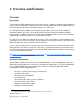
S S S S S S S S S S S S S S S S S S S S S S S S S S S S S S S S S S S S S S S S 1: Overview and Features Overview Description The standard XLi IEEE 1588 Clock, also referred to as the “XLi”, provides a complete implementation of a Precise Time Protocol (PTP) “ordinary clock” over a dedicated IEEE 1588 card. The IEEE 1588 card can be configured to operate as a PTP grandmaster or as a PTP slave.
S 1 S S S S S S S S S S S S S S S S S S S S S S S S S S S S S S S S S S S S S S S Only the features listed above are supported for the XLi IEEE 1588 clock. At the time of this writing, none of the other options for the XLi Time and Frequency system are supported on the XLi IEEE 1588 clock. Contact Symmetricom Sales to obtain a special supported configuration of the XLi IEEE 1588 clock. For contact information, please see Sales and Customer Assistance (page 197).
S S S S S S S S S S S S S S S S S S S S S S S S S S S S S S S S S S S S S S S S Network Port (“1588”) A IEEE1588-compliant “ordinary clock” is available from a stand-alone Ethernet port, labelled “1588”, on the rear panel of the IEEE 1588 card. Type: Standard RJ-45 8-pin connector, 100 Base-T Qty: 1 Packet type Ethernet DIX II (RFC 894) Protocols IPV4, IEEE1588, 802.
S S S S S S S S S S S S S S S S S S S S S S S S S S S S S S S S S S S S S S S S LEDs The following LEDs are available on the IEEE 1588 card rear panel: 1 • • • • • Network Port (1588), Green and Amber LEDs illuminate when receiving or transmitting network traffic. PPS: LED illuminates (green) while the SYNC OUT signal is high. See “PPS Output (“SYNC OUT”)” on page 3. TX: LED illuminates (green) with transmission of a PTP packet.
S S S S S S S S S S S S S S S S S S S S S S S S S S S S S S S S S S S S S S S S Specifications Frequency 1575.
S S S S S S S S S S S S S S S S S S S S S S S S S S S S S S S S S S S S S S S S Standard 110 VAC Power Supply 1 The XLi’s internal fault detector can monitor the three output voltages from the primary and the secondary power supplies. With the Primary Power or Secondary Power indicators in F73 enabled, a 10% decrease in any of the output voltages triggers an alarm. See “F73 – Alarm Control / Status” on page 69.
S S S S S S S S S S S S S S S S S S S S S S S S S S S S S S S S S S S S S S S S Clock Architecture Figures 1 and 2 on the following pages provide a simplified view of the standard XLi's clock architecture. 16.384 MHz Osc. PLL 2 Aux Ref 1 PPS A 1PPS B Code Input Aux Ref 1,5,10 MHz Phase Measurement DAC Clock DPLL 10 MHz Osc.
S S S S S S S S S S S Display 1 S S S S S S S S S S S S Keypad Display/Keypad Interface S S S S S S S S S S S S S Oscillator Rb Power 10 MHz Power, Vc S S S S I/O Backplane Interface Power I/O Power I/O Power Supply AC +5 V, +/- 12 V Power Supply DC +5 V, +/- 12 V Option T&F CPU 110/220 AC 9-18 VDC 18-36 VDC 36-72 VDC User I/O User I/O Figure 2: Interface Architecture Block Diagram 8 XLi IEEE 1588 Clock 997-01510-03, Rev.
S S S S S S S S S S S S S S S S S S S S S S S S S S S S S S S S S S S S S S S S 2: System Specifications Mechanical/Environmental Power: 95-260 VAC, 47 to 440 Hz Operating Temperature: 0 °C to +50 °C (+32 °F to +122 °F) Maximum Rate of Change: 8 °C per hour Storage Temperature: -55 °C to +85 °C (-67 °F to +185 °F) Humidity: To 95% non-condensing Operating Altitude: Maximum 4 km (2.49 mi. or 13147 ft.
S S S S S S S S S S S S S S S S S S S S S S S S S S S S S S S S S S S S S S S S System Time & Frequency Accuracy 1 The tables below describe system clock accuracy while locked to the reference source indicated. Currently, GPS is the only supported reference source.
S S S S S S S S S S S S S S S S S S S S S S S S S S S S S S S S S S S S S S S S Standard Inputs and Outputs The following specifications describe the standard (as opposed to optional) inputs and outputs on the standard configuration of the XLi. Serial I/O Port The standard serial data port is a bi-directional EIA standard RS-232C interface. The serial data port is configured via the Keypad / Display and Standard network port.
S S S S S S S S S S S S S S S S S S S S S S S S S S S S S S S S S S S S S S S S J1 Input – Time Interval - Event Time 1 The Time Interval - Event Time (TIET) option measures a 1 PPS or Event input signal on J1 against the XLi derived time. The rising edge of the pulse is measured against XLi time with 5 ns resolution. Pulse Width 100 ns, min. Active Edge: Rising Amplitude (DC): Logic Low: < 1.25V and Min. 300mV Logic Hi: >1.
S S S S S S S S S S S S S S S S S S S S S S S S S S S S S S S S S S S S S S S S J3 Input – Auxiliary Reference Auxiliary Reference (Aux Ref): Frequency: 1, 5, 10 MHz Amplitude: 1 Vp-p to 10 Vp-p at 1 kΩ to ground Amplitude: 1 Vp-p to 3 Vp-p at 50 Ω to ground Impedance: Configurable 1 kΩ or 50 Ω to ground SNR: >20db Quantity: 1 Connector: Female BNC Factory Configuration: Disabled 2 See “F113 – J3 Input Configuration (Aux Ref)” on page 104.
S S S S S S S S S S S S S S S S S S S S S S S S S S S S S S S S S S S S S S S S ALARM Output 1 High Z: Power off High Z: Alarm (enabled alarm fault) Low Z: Normal (no enabled alarm faults) Drive: Open Collector Max. Voltage: 25 VDC Max. Current: 50 mA Quantity: 1 Connector: Female BNC Certifications UL, C-UL: UL 1950/CSA 22.
S S S S S S S S S S S S S S S S S S S S S S S S S S S S S S S S S S S S S S S S 3: Installation and Set-up In a nutshell: • Install the GPS antenna outdoors, run the cable, and connect it to the XLi’s GPS receiver. • Make the following connections to the XLi (all cables supplied): - From the network to the NET port (for access to the command line and web interfaces). - From an AC outlet to the XLi’s AC power supply.
S 1 S S S S S S S S S S S S S S S S S S S S S S S S S S S S S S S S S S S S S S S Blocked signals and multipath cancellation significantly increase GPS acquisition time. Multipath cancellation is caused by reflected signals that reach the antenna out of phase with the direct signal. Multipath cancellation and blocked signals are typically caused by vertical reflective objects positioned to the side and above the antenna.
S S S S S S S S S S S S S S S S S S S S S S S S S S S S S S S S S S S S S S S S 2 1 5 Figure 3: L1 GPS Antenna - methods for cabling and mounting GPS Signal Strength Requirements Refer to Figure 4:The required gain at the GPS receiver’s ANTENNA connector is greater than 20 dB and less than 36 dB. A 150 foot length of RG-59 coax cable of has a loss of 16-21 dB, which meets this requirement. Abide by the minimum input gain requirements if using other cable types.
S S S S S S S S S S S S S S S S S S S S S S S S S S S S S S S S S S S S S S S S VSWR, and input impedance also affect system performance. Symmetricom recommends using the standard 12-volt capable antenna and cable provided with the GPS receiver. 1 Figure 4: GPS Signal Strength Requirements Connect the GPS antenna cable to the GPS receiver’s ANTENNA connector at the rear of the XLi. Note: Use a 12-volt capable GPS antenna.
S S S S S S S S S S S S S S S S S S S S S S S S S S S S S S S S S S S S S S S S Configuring Network Settings The following steps are required to make the XLi’s Main CPU card operational on a network. Do this if you plan on using the command line or web interface to manage the XLi over the network.
S S S • 1 S S S S S S S S S S S S S S S S S S S S S S S S S S S S S S S S S S S S S antenna is not in an optimal site or there is a problem with the antenna cable connections. If this delay is unexpected, consider relocating the GPS antenna to a better site or troubleshooting the GPS antenna cable. Press the STATUS key on the front panel. The display should show “LOCKED GPS PRI” without an asterisk (“*”).
S S S • • S S S S S S S S S S S S S S S S S S S S S S S S S S S S S S S S S S S S S SLAVE SYNC THRESHOLD - 5 microsec PTP PREFERRED MASTER - DISABLE Note: When two IEEE 1588 cards are present, use the up/down arrow keys to select the PTP master in Option Bay 4 before making changes.
S S S S S S S S S S S S S S S S S S S S S S S S S S S S S S S S S S S S S S S S Note: The IEEE 1588 card configured as a PTP slave relies on TAI as the time scale of the PTP master. Distributing non-TAI time over PTP while the PTP slave is a reference source will have a predictable effect on the XLi’s system time. 1 Note: Later on, when reconfiguring the IEEE 1588 card as a PTP master, use F119 to set the GPS receiver as the PRIMARY reference source.
S S S • S S S S S S S S S S S S S S S S S S S S S S S S S S S S S S S S S S S S S Secure the brackets to the rack using rack mount screws. 2 Note: Ensure that the ambient operating temperature does not exceed +50° C. Install the XLi chassis so that the top and bottom holes are unobstructed and have sufficient clearance to allow 6 cfm of air to pass through the chassis.
S S S S S S S S S S S S S S S S S S S S S S S S S S S S S S S S S S S S S S S S 1 24 XLi IEEE 1588 Clock 997-01510-03, Rev.
S S S S S S S S S S S S S S S S S S S S S S S S S S S S S S S S S S S S S S S S 4: User Interfaces The XLi features two user interfaces for controlling the XLi’s functions: • • • A keypad/display interface on the front panel of the XLi A command line interface, available through the serial and network ports A web interface, available from a browser connected to the XLi’s network port. There is also an Alarm Status LED on the front panel.
S S S S S S S S S S S S S S S S S S S S S S S S S S S S S S S S S S S S S S S S Time Display related functions: • 1 Select between the 12 or 24 hour format displayed: “F2 – 12/24 Hour Format” on page 39. Time related functions: • • • “F1 – Time Zone Offset” on page 38 “F3 – Time & Date” on page 40 “F66 – Daylight Saving Time (DST) Mode” on page 63 Status Display The Status Display comes up automatically when the XLi is rebooted.
S S S S S S S S S S S S S S S S S S S S S S S S S S S S S S S S S S S S S S S S Pressing the MENU key on the front of the XLi displays the first function, F1: TIME ZONE OFFSET: F1: TIME ZONE OFFSET Pressing the UP ARROW key increments to the next function, F2 - 12/24 HOUR FORMAT, and so on. Pressing the DOWN ARROW key skips to the highest available function, F126 OPTIONS KEY ENTRY, and, from there, decrements through the functions.
S S S S S S S S S S S S S S S S S S S S S S S S S S S S S S S S S S S S S S S S Keypad Examples The following examples show how to use the keypad effectively.
S S S S S S S S S S S S S S S S S S S S S S S S S S S S S S S S S S S S S S S S To enter numeric values in a function: Press Result ENTER Displays the “FUNCTION” prompt 3 Enters “3” as the function number ENTER Opens Function 3, displays the first screen, “TIME MODE – LOCAL” ENTER Displays the second parameter, “DATE-TIME…/- /” 05152002 Enters May 15, 2002 as today’s date.
S S S S S S S S S S S S S S S S S S S S S S S S S S S S S S S S S S S S S S S S Logging Out You can log out using any of the following commands: logout logoff exit quit 1 Changing Username and Password To change the user name and password, use the following commands: • • “F100 P – Change User Password” on page 95 “F100 PN – Change User Name” on page 97 To reset a lost or forgotten operator username/password, use F100 P and F100 PN commands from the command line in
S S S S S S S S S S S S S S S S S S S S S S S S S S S S S S S S S S S S S S S S Network port session: WELCOME TO SYMMETRICOM NETWORK INTERFACE! USER NAME: operator PASSWORD: ***** NETWORK INTERFACE 192-8001 (c) 1998 - 2003 SYMMETRICOM ALL RIGHTS RESERVED LOGIN SUCCESSFUL! >f100 ic f100 IP:192.168.46.150 SM:255.255.255.0 G:192.168.46.
S S S S S S S S S S S S S S S S S S S S S S S S S S S S S S S S S S S S S S S S The web interface manages this distinction by providing two sets of web pages. Pages available from the XLi Admin Homepage display status information and let the user change the XLi’s configuration settings. Pages available from the XLi User Homepage only display status information. 1 Administrative users (e.g.
S S S • • S S S S S S S S S S S S S S S S S S S S S S S S S S S S S S S S S S S S S settings, alarms, and SNMP). System I/O - the status and configuration of the input and output connectors on the rear of the main CPU card (e.g., communication settings, code out, J1, J2, and J3). Subsystem - configuration of the option cards located in the option bays Under Subsystem, the XLi names CPU-aware option cards to the right of the option bay where they are located.
S S S S S S S S S S S S S S S S S S S S S S S S S S S S S S S S S S S S S S S S 1 34 XLi IEEE 1588 Clock 997-01510-03, Rev.
S S S S S S S S S S S S S S S S S S S S S S S S S S S S S S S S S S S S S S S S 5: Function Reference Function Summary The following summary lists all the XLi functions, identifies the user interfaces from which each one is available, and provides a brief description of the function.
S S S S S S S S S S S S S S S S S S S S S S S S S S S S S S S S S S S S S S S F66 – Daylight Saving Time (DST) Mode K,N,S,W Schedule when DST starts and ends (Local time only) F69 – Time Mode K,N,S,W Set the time scale (TAI, GPS, UTC, Standard, Local) output by the IEEE 1588 card and displayed on the front panel of the XLi. (TAI is the recommended setting).
S S S S S S S S S S S S S S S S S S S S S S S S S S S S S S S S S S S S S S S F100 K I L L – Reboot N,S Reboot the XLi F100 P – Change User Password N,S,W Change the XLi password F100 PI – PING N,S Ping from the XLi to another host on the network F100 PN – Change User Name N,S,W Change the User Name F108 – Oscillator Configuration K,N,S,W View the oscillator type F110 – J1 Input (TIET) K,N,S,W Configure the J1 input connector.
S S S S S S S S S S S S S S S S S S S S S S S S S S S S S S S S S S S S S S S S F1 – Time Zone Offset 1 Use function F1 to display and set the time zone offset between your Standard Time zone and Universal Time Coordinated (UTC). Refer to “F: World Map of Time Zones:” on page 193. F1 is the basis for Standard Time and Local Time used by F69. For an expanded explanation of Local, Standard, UTC, TAI, and GPS time, see “F69 – Time Mode” on page 65.
S S S S S S S S S S S S S S S S S S S S S S S S S S S S S S S S S S S S S S S S XLi responds: OK To verify the change, enter: F1 XLi Responds: F1 –8:00 2 F2 – 12/24 Hour Format Use function F2 to make 12 or 24-hour time notation available from: • • • Keypad/Display Interface (page 25) F8 - Continuous Time Once-per-Second (page 46) F9 - Time On Request (page 49) 1 And separately from: • CODE – Time Code Output (page 13) F2 does not affect t
S S S S S S S S S S S S S S S S S S S S S S S S S S S S S S S S S S S S S S S S The XLi responds: F2DI 1 where: F = ASCII character F. 02 = Function number. = ASCII space character (one or more). D = ASCII character for Display format. = 12 or 24. I = ASCII character for IRIG format = Carriage return character. = Line feed character.
S S S S S S S S S S S S S S S S S S S S S S S S S S S S S S S S S S S S S S S S TIME MODE selects which time scale (TAI, Local, Standard, GPS, UTC) is being entered by the user. The XLi, translates the user entry into its equivalents in other time scales. For example, if Local time is 5 hours relative to UTC, entering LOCAL - 07/14/2006 - 10:47:10 in F3 shows up on the front keypad display as UTC 198:15:47:10.
S 1 S S S S S S S S S S S S S S S = two-digit seconds. = carriage return character. = line feed character. S S S S S S S S S S S S S S S S S S S S S S S S For example, to display the date and time, send: F3 XLi responds: F3 UTC 01/01/2002 00:05:34 To set the time and date, send: F3 UTC 07/14/2002 18:20:30 Only valid times and dates are accepted.
S S S S S S S S S S S S S S S S S S S S S S S S S S S S S S S S S S S S S S S S where: F = ASCII character F. 04 = function number. = ASCII space character (one or more). = One or more separator characters: either space, comma or tab.
S 1 S S S S S S S S S S S S S S S S S S S S S S S S S S S S S S S S S S S S S S S The XLi estimates the time error based on the oscillator-type and on the degree of steering (DAC value) applied to the oscillator before the reference source became unavailable. As time error grows and exceeds the thresholds of each time-quality flag, the XLi generates a different time-quality indicator.
S S S S S S S S S S S S S S S S S S S S S S S S S S S S S S S S S S S S S S S S where: F = ASCII character F 05 = function number = ASCII space character (one or more) = one or more separator characters; either space, comma or tab = ENABLE or DISABLE = one error threshold in nanoseconds, 1 to 11 digits with or without leading zeros = carriage return character = line feed character 2 For example, to display the time qua
S S S S S S S S S S S S S S S S S S S S S S S S S S S S S S S S S S S S S S S S XLi responds: F6 1 where: F = ASCII character F 6 = function number = ASCII space character (one or more) = ENABLE or DISABLE = carriage return character = line feed character For example, to display the Keypad Lock status, send: F6 XLi responds: F6 DISABLE To enable Keypad Lock, send the following string: F6 ENABLE XLi
S S S • • • S S S S S S S S S S S S S S S S S S S S S S S S S S S S S S S S S S S S S F5 – Time-Quality Setup (page 43) F11 - Time Output Format (page 50) F69 – Time Mode (page 65) The Format of the F8 Output String The factory setting for the output string format is as follows: DDD:HH:MM:SSQ 2 where: = ASCII Start-of-Heading character = ASCII Carriage Return character = ASCII Line Feed character DDD = day-of-year. HH = hours.
S S S S S S S S S S S S S S S S S S S S S S S S S S S S S S S S S S S S S S S S While Synchronizing to a Reference Source 1 Following startup, the user should avoid using F8 outputs until the XLi has acquired and locked to a timing reference source such as GPS PRI (when F131 is set to PTP MASTER) or the IEEE 1588 card (when F131 is set to PTP SLAVE PRIMARY).
S S S S S S S S S S S S S S S S S S S S S S S S S S S S S S S S S S S S S S S S F9 - Time On Request This function is available through the command line interface only. It is not available from the keypad. Use function F9 to record the exact time the XLi receives a request from the user. Enter the command "F9" to prepare the XLi for the user's request. At the desired moment, send the request to the XLi by entering an upper case "T".
S S S S S S S S S S S S S S S S S S S S S S S S S S S S S S S S S S S S S S S S F9 Then, to request the current time, enter SHIFT-T on your keyboard. ("T" does not appear). XLi responds: 1 128:20:30:04.357* To exit F9 press Ctrl-C on your keyboard. F11 - Time Output Format Use function F11 to change the format of the F8 and F9 time output strings.
S S S S S S S S S S S S S S S S S S S S S S S S S S S S S S S S S S S S S S S S The time quality character, "Q", is one of the following characters: SPACE = Time error is less than time quality flag 1's threshold .
S S S S S S S S S S S S S S S S S S S S S S S S S S S S S S S S S S S S S S S S F11 DDDDHHHMMMSSSmmmQ With the new formatting, F8 displays: 1 128D16H41M27* And F9 displays: 365D16H45M22S680* F13 – Time Error Use function F13 to request the estimated worst-case time error due to oscillator drift during periods of unlock from a reference source. See “System Time & Frequency Accuracy” on page 10 for more information on time error for different reference sources.
S S S S S S S S S S S S S S S S S S S S S S S S S S S S S S S S S S S S S S S S F18 – Software Version Request Use function F18 to display the current firmware version numbers of the firmware in the XLi: • • • • • Bootloader Software (firmware) File System Project Rev # FPGA 2 Command Line Use Command Line Function F18 to obtain the system’s firmware version information.
S S S • • 1 • S S S S S S S S S S S S S S S S S S S S S S S S S S S S S S S S S S S S S Display the option bay location of the GPS receiver(s). If multiple GPS receivers are available, use the UP/DOWN ARROW keys to select a receiver. Select the positional coordinate system, Latitude Longitude Altitude (LLA) or XYZ (EarthCentered, Earth-Fixed XYZ coordinates). If LLA is selected, Altitude Mode shows the elevation in given meters.
S S S S S S S S S S S S S S S S S S S S S S S S S S S S S S S S S S S S S S S S XLi responds: F50 B1 N 38d23'51.3" W 122d42'53.
S 1 S S S S S S S S S S S S S S S S S S S S S S S S S S S S S S S S S S S S S S S 59 GPS antenna cable supplied with the XLi. If the GPS antenna is connected using a different antenna length, calculate the new value using the multiple given below and adjust the value of F51. If using an optional Down/Up Converter, consult that product’s documentation for directions on setting the correct cable delay. F51 Guidelines: • • • For RG-59: multiply the cable length by 1.
S S S S S S S S S S S S S S S S S S S S S S S S S S S S S S S S S S S S S S S S To set the antenna cable delay for an option card, use the following format: F51BNS For example, to set the antenna cable delay for the GPS card in option bay 4 to 100 ns, enter: F51 B4 100NS XLi responds: OK 2 F52 – Distribution Cable Delay Use function F52 to display or set the distribution cable delay for the time code and 1 PPS outputs.
S S S S S S S S S S S S S S S S S S S S S S S S S S S S S S S S S S S S S S S S where: 1 F = ASCII character F (f or F for input string). 52 = the function number. = one or more space characters.
S S S S S S S S S S S S S S S S S S S S S S S S S S S S S S S S S S S S S S S S If an GPS C/A Receiver is available, F53 displays: GPS M12 AVAILABILITY OPTION BAY # Where # is the option bay number the card is located in. If more than one GPS C/A Receiver is present, use the UP/DOWN ARROW buttons to select the option bay location of a specific card.
S S S S S S S S S S S S S S S S S S S S S S S S S S S S S S S S S S S S S S S S Example response: F53 B1 AUTO MODE 1 (or DYNAMIC MODE) To set the GPS Operation Mode, enter a command using the following format: F53B where equals “DYNAMIC MODE” or “AUTO MODE”.
S S S S S S S S S S S S S S S S S S S S S S S S S S S S S S S S S S S S S S S S F60B XLi responds with approximately 32 lines that use the following format: F60Bprn tracked current where: F60 = ASCII string indicating function F60. = ASCII space character one or more. B = ASCII letter to denote Option Bay number follows = Option Bay Number, 1 through 4.
S S S F60 F60 F60 F60 F60 F60 F60 F60 F60 F60 F60 F60 F60 F60 F60 1 S B1 B1 B1 B1 B1 B1 B1 B1 B1 B1 B1 B1 B1 B1 B1 S S S prn18 prn19 prn20 prn21 prn22 prn23 prn24 prn25 prn26 prn27 prn28 prn29 prn30 prn31 prn32 S S S S S S unknown unknown unknown unknown good current unknown unknown unknown unknown good current unknown unknown unknown unknown unknown S S S S S S S S S S S S S S S S S S S S S S S S S S S -164dBW -156dBW Similarly, to display a list of the curren
S S S S S S S S S S S S S S S S S S S S S S S S S S S S S S S S S S S S S S S S F66 – Daylight Saving Time (DST) Mode Use function F66 to enable or disable Daylight Saving Time (DST), and to schedule when Local time enters and leaves DST. The factory setting for F66 is Manual (i.e., DST On). The hour for entering/ leaving DST is given in the 24-hour format. Entering/leaving DST can be scheduled for any hour of the day, any day of the year.
S S S S S S S S S S S S S S S S S S S S S S S S S S S S S S S S S S S S S S S S where: 1 = time to enter DST in 24-hour format. = one or more separator characters, either space comma or tab characters. For output strings this will be a single space character. = which week to enter DST, 1, 2, 3, 4 or 0 (for last). = day of week to enter DST, 1 through 7 where Sunday is 1.
S S S S S S S S S S S S S S S S S S S S S S S S S S S S S S S S S S S S S S S S F69 – Time Mode Use function F69 to select the time mode (time scale) shown or output by: • • • • The XLi’s front panel display The following command line functions (network and serial port): - “F8 - Continuous Time Once-per-Second” on page 46 - “F9 - Time On Request” on page 49 The CODE output on the Main CPU card.
S S S S S S S S S S S S S S S S S S S S S S S S S S S S S S S S S S S S S S S S Related functions: • • • • 1 “F1 – Time Zone Offset” on page 38 “F66 – Daylight Saving Time (DST) Mode” on page 63 “F8 - Continuous Time Once-per-Second” on page 46 “F9 - Time On Request” on page 49 Command Line Local Time modifies UTC time to include the Time Zone and Daylight Saving Time adjustments, if enabled by the user.
S S S S S S S S S S S S S S S S S S S S S S S S S S S S S S S S S S S S S S S S where: F = ASCII character F. 69 = Function number. = ASCII space character. = Time Type. Either GPS, UTC, TAI, LOCAL, or STANDARD. = carriage return character. = line feed character.
S S S S S S S S S S S S S S S S S S S S S S S S S S S S S S S S S S S S S S S S where: 1 F = ASCII string indicating function F71 = ASCII space character one or more. = multiplier, 4 digits with decimal point. E = ASCII character E for exponent. s = ASCII character s for seconds abbreviation = - for negative or for positive. = 2 digit exponent.
S S S S S S S S S S S S S S S S S S S S S S S S S S S S S S S S S S S S S S S S F72 The XLi responds: F72PLL: CLK: PWR1: PWR2: OSC: where: F = ASCII character F 72 = function number = ASCII space character one or more.
S S S • • • • 1 S S S S S S S S S S S S S S S S S S S S S S S S S S S S S S S S S S S S S See the state of the Alarm Latch for each indicator Clear the Alarm Latch for all indicators Enable or disable blinking of the Alarm Status LED on the front panel while it is green or amber Set the values for Time Threshold, Timeout Delay, and Power-On Alarm Suppress The following table summarizes F73’s alarm indicators and parameters, as well as the factory settings for an XL
S S S S S S S S S S S S S S S S S S S S S S S S S S S S S S S S S S S S S S S S Alarms - General Information With Alarm Disabled, an F73 indicator does not trigger and alarm when it enters an Unlocked or Fault state. With Alarm Enabled, an F73 indicator triggers an alarm when it enters an Unlocked or Fault state, and the following events take place: • • • The Alarm Status LED changes color from green to amber or red (See “Alarm Status LED” on page 25.
S S S S S S S S S S S S S S S S S S S S S S S S S S S S S S S S S S S S S S S S The keyboard/display interface shows the Alarm Latch as an asterisk next to an indicator, as follows: GPS PRI OK 1 ∗ ALARM ENABLED Power On Alarm Suppress Power On Alarm Suppress prevents all F73 alarms from occurring for a specified interval after the unit starts up. The factory setting is 300 seconds (five minutes).
S S S S S S S S S S S S S S S S S S S = ASCII character S, Status delimiter = 'L' Locked S S S S S S S S S S S S S S S S S S S S S S 'U' Unlocked = 'A' Clock IRIG A 'B' Clock IRIG B 'G' Clock IRIG G 'N' lock NASA 36 'P' Clock Primary 2 'S' Clock Secondary 'R' Clock to Aux Ref 'F' None 1 = '-' PLL Synthesizer Locked 'C' PLL Synthesizer Unlocked 2 = '-' LPN PLL Locked 1 'L' LPN PLL Unlocked 3 = '-' Primary OK 'P' Primary Fault 4 = '-' Se
S S S S S S S S S S S S S S S S S S S S S S S S S S S S S S S S S S S S S S S S 'U' Time error Fault = '-' Timeout OK D 1 'T' Timeout Fault = '-' NTP OK E 'N' NTP Fault To see the states the Alarm Latches for all of the indicators, enter: F73LATCH XLi replies: F73LATCH<123> To clear the Alarm Latches, enter: F73CLEARALARMLATCH XLi replies: OK The command line uses a ‘mask’ to enable or disable each indicator’s alarm.
S S S S S S S S S S S S S S S S S S S S S S S S S S S S S S S S S S S S S S S S The following reference table identifies the indicators that correspond to each position in F73 mask syntax. Use this table when entering or reviewing MASK settings.
S S S S S S S S S S S S S S S S S S S S S S S S S S S S S S S S S S S S S S S S To view the Time Threshold setting, enter: F73THRESHOLD 1 XLi replies: F73THRESHOLDns where is the time error threshold in ns To set a new Time Threshold, enter a new value for (Range 0 to 99,999 ns), as follows: F73THRESHOLD XLi replies: OK To view Timeout Delay, enter: F73TIMEOUT
S S S S S S S S S S S S S S S S S S S S S S S S S S S S S S S S S S S S S S S S The XLi responds: F73 POWER-ON MINOR ALARM SUPPRESS 300 To set a new Power-On Alarm Suppress value, enter the following string, replacing with the number of seconds (Range 0 to 86,400 seconds), enter: F73 SUPPRESS The XLi responds: OK 2 F74 – Clock Source Control Use function F74 to select the primary and secondary reference sources and configure the fail-over seque
S S S S S S S S S S S S S S S S S S S S S S S S S S S S S S S S S S S S S S S S Command Line To display the current settings, enter: 1 F74 XLi responds, using the following format: F74 where: F = ASCII character F. 74 = function number. = Space = Clock Source: • PRI • SEC • PRI-SEC-SEC • PRI-SEC-PRI • PRI-NSEC-PRI = carriage return character. = line feed character.
S S S S S S S S S S S S S S S S S S S S S S S S S S S S S S S S S S S S S S S S The factory settings for F90 are IRIG-B and AM. Although the factory configuration outputs UTC time in 24-hour format, the following can be used to modify the code output of F90 for non-standard applications: • • “F2 – 12/24 Hour Format” on page 39 selects between a 12 or 24-hour time format.
S S S S S S S S S S S S S S S S S S S S S S S S S S S S S S S S S S S S S S S S F100 – Network Port Configuration & XLi Firmware F100 provides two groups of commands: 1 • • Group 1, available through the keypad/display and the command line, provides access to network port settings and hardware/Firmware status information.
S S S S S S S S S S S S S S S S S S S S S S S S S S S S S S S S S S S S S S S S The following table gives the command line equivalents for each of the preceding parameters: Description “F100” followed by: Comments Ethernet address (MAC address) EA Displays information IP Address IP Displays, configures and reboots Subnet Mask SM Displays, configures and reboots Default Gateway G Displays, configures and reboots 2 IP Address, Subnet Mask, IC and Default
S S S S S S S S S S S S S S S S S S S S S S S S S S S S S S S S S S S S S S S S F100 EA – Ethernet Address 1 Use function F100 EA to display the Ethernet Address (MAC Address) (Note: An Ethernet or MAC Address is not the same thing as an IP Address), a fixed, six-byte, hexadecimal value specific to the unit’s standard network port. The first three bytes are registered to Symmetricom Inc.; the last three bytes are the hex value identifying the network port.
S S S S S S S S S S S S S S S S S S S S S S S S S S S S S S S S S S S S S S S S For example, enter: F100 IP 206.54.0.21 XLi responds: OK RESETING THE UNIT PLEASE WAIT… To obtain the IP address of the unit Standard network port, enter: 2 F100 IP The XLi responds (example): F100 IP 206.54.0.21 1 The three commands, F100 IP, F100 SM, and F100 G, can be concatenated to set all three values simultaneously.
S S S S S S S S S S S S S S S S S S S S S S S S S S S S S S S S S S S S S S S S where: 1 F = ASCII character F 100 = unit function number = space IP = specify IP command = dotted decimal address (0 to 255) = input line terminator For example, enter: F100 SM 255.255.255.
S S S S S S S S S S S S S S S S S S S S S S S S S S S S S S S S S S S S S S S S where: F = ASCII character F 100 = unit function number = space IP = specify IP command = dotted decimal address (0 to 255) = input line terminator 2 For example, enter: F100 G 206.54.0.
S S S S S S S S S S S S S S S S S S S S S S S S S S S S S S S S S S S S S S S S selecting between 10 Base-T and Auto. If you have questions about your unit, contact H: Sales and Customer Assistance (page 197).
S S S S S S S S S S S S S S S S S S S S S S S S S S S S S S S S S S S S S S S S where: F = ASCII character F 100 = unit function number = space LOCK = specify LOCK command = input line terminator For example, enter: 2 F100 LOCK To users on the serial port, XLi responds: OK 1 Or, to users on the network port, XLi gives the following response and then closes the port: GOODBYE.
S S S S S S S S S S S S S S S S S S S S S S S S S S S S S S S S S S S S S S S S XLi responds: F100 L LOCKED 1 or F100 L UNLOCKED F100 ST – Self Test Status Use function F100 ST to display whether the Self Test Status parameters passed or failed. The parameters include: flash-memory checksum test, nonvolatile (NV) RAM, Serial Port, and version check.
S S S S S S S S S S S S S S S S S S S S S S S S S S S S S S S S S S S S S S S S where: F = ASCII character F 100 = Unit function number = Space ST = Specify ST command FLASH/CRC: = Specify flash checksum result RAM: = Specify RAM test result SERIAL: = Specify Serial Port test result. 2 NVRAM VER: = Specify version test result.
S S S S S S S S S S S S S S S S S S S S S S S S S S S S S S S S S S S S S S S S To write the BootLoader to the flash, send the F100 BH command with the FTP host, file path and name, and then enter: 1 F100 BUB XLi responds: OK For example: >f100 bub OK BURNING FILE 192-8000.
S S S S S S S S S S S S S S S S S S S S S S S S S S S S S S S S S S S S S S S S SEC: 14 RE: 0 SEC: 15 RE: 0 SEC: 16 RE: 0 SEC: 17 RE: 0 SEC: 18 RE: 0 SEC: 19 RE: 0 SEC: 20 RE: 0 SEC: 21 RE: 0 SEC: 22 RE: 0 FLASH SUCCESSFULLY PROGRAMMED CRC32 = 0x2D9A260A F100 BF – Burn File System 2 Note: See “B: Upgrading System Firmware” on page 145. Use function F100 BF to burn file system when upgrading firmware, to write a file system to the flash memory.
S S S S S S S S S S S S S S S S S S S S S S S S S S S S S S S S S S S S S S S S The existence of the FPGA program file on the FTP server and an Ethernet connection is checked when the command is issued. 1 To write the FPGA program to the flash, send the F100 BH command with the FTP host, file path and name, and then send the following command: F100 BUFP This command is only valid for XLi with an 86-8000 Rev. G or higher CPU card.
S S S S S S S S S S S S S S S S S S S S S S S S S S S S S S S S S S S S S S S S Notes: • See “A: Using F100 Configuration” on page 141. F100 CONFIG GET instructs the XLi unit to transfer its SNMP configuration file to an FTP server. After editing the SNMP configuration file on the FTP server, the user transfers them back to the XLi using the F100 CONFIG SET command. Open a Telnet session with the XLi and enter the commands below.
S S S S S S S S S S S S S S S S S S S S S S S S S S S S S S S S S S S S S S S S Units are shipped to the customer with no jumper installed. The jumper is used by Symmetricom technicians to test and configure the unit. With this jumper installed, the operation and integrity of the XLi are compromised. 1 Warning: Please do not run the XLi with the jumper, unless specifically directed to do so by a qualified Symmetricom technician.
S S S S S S S S S S S S S S S S S S S S S S S S S S S S S S S S S S S S S S S S In a network port session, rebooting the XLi terminates the network port session; open a new network port session when the XLi has finished rebooting. In a serial port session, the XLi displays text similar to the following example when the XLi has finished rebooting and is ready to receive additional commands: >SYSTEM POWER ON SELF TEST RESULTS: SERIAL LOOPBACK TEST PASSED.
S S S S S S S S S S S S S S S S S S S S S S S S S S S S S S S S S S S S S S S S where: 1 F = ASCII character F 100 = unit function number = space P = specify Password command = input line terminator The XLi responds: ENTER NEW USER PASSWORD: When you enter the new password, the XLi responds: CONFIRM NEW USER PASSWORD: Enter the same new password again, to confirm the spelling.
S S S S S S S S S S S S S S S S S S S S S S S S S S S S S S S S S S S S S S S S To test if the XLi’s network port has a good connection, enter the following using in a serial port session: >f100 PI The Xli responds: PING : REMOTE HOST FOUND. or it responds: PING : REMOTE HOST NOT FOUND. 2 F100 PN – Change User Name Use function F100 PN to change a user name.
S S S S S S S S S S S S S S S S S S S S S S S S S S S S S S S S S S S S S S S S In this case, the old user name will be used for the next login using the command line interface. 1 If you have forgotten the operator or guest user name and/or password, use “Bootloader Mode” to change them. In Bootloader Mode, log in using the factory set user names (“operator”, ”guest”) and passwords (See “Command Line Interface” on page 29.).
S S S S S S S S S S S S S S S S S S S S S S S S S S S S S S S S S S S S S S S S where: F = ASCII character F 108 = Function number = ASCII space character one or more = Carriage Return, equivalent to pressing the Enter key on a keyboard = Oscillator type: TCVCXO, OCXO, HIGH (High Stability OCXO), or RUBIDIUM For example, enter the following string: 2 F108 The XLi responds (example): F108 OSCILLATOR CONFIG TCVCXO 1 F110 – J1 Inp
S S S • • 1 • • S S S S S S S S S S S S S S S S S S S S S S S S S S S S S S S S S S S S S Input Polarity: Positive, Negative Propagation Delay: (Range 0 to 99999 μS in 1 μS steps) (Factory setting: 1 μS) Compensates for delay caused by cable length on the J1 input. IRIG Mode: (Sync Gen) Error Bypass: (Off, 1-10 Frames) (Factory setting: 3 frames) Is used when the IRIG input is intermittent or has a low signal to noise ratio (SNR).
S S S S S S S S S S S S S S S S S S S S S S S S S S S S S S S S S S S S S S S S F110 Or F110TIET (when TIET option is enabled and J1 is set to TIET) Where the F110 entry and request formats are defined as: 2 F = ASCII character F. 110 = function number.
S S S S S S S S S S S S S S S S S S S S S S S S S S S S S S S S S S S S S S S S Or F110 TIET 50 POSITIVE 1 To set the J1 Input Configuration, make a command line entry using the same format as the XLi response above. Only valid values are accepted.
S S S S S S S S S S S S S S S S S S S S S S S S S S S S S S S S S S S S S S S S Use function F111 to configure the J2 Output to generate rates (listed below). The following rates are available as a standard feature: 1 PPS, 10 PPS, 100 PPS, 1 kPPS, 10 kPPS, 1 MPPS, 5 MPPS, 10 MPPS. The factory setting is 10 MPPS. For J2 specifications, see “J2 Output – Rate Out” on page 12.
S S S S S S S S S S S S S S S S S S S S S S S S S S S S S S S S S S S S S S S S Setting the J2 Output Configuration 1 To set the J2 Output Configuration, send a character string with the previously defined F111 entry format to the Serial/Network port. Only valid values are accepted. The J2 Output Configuration can be set to specify one of several predetermined rates. The following sections provide examples (and some explanations) for each.
S S S S S S S S S S S S S S S S S S S S S S S S S S S S S S S S S S S S S S S S When the XLi reacquires a time reference source and is steering its own internal oscillator, it stops using Aux Ref as its frequency reference. For Aux Ref to work: • • • • The Aux Ref frequency source must be connected to the J3 input.
S S S S S S S S S S S S S S S S S S S S S S S S S S S S S S S S S S S S S S S S F113 AUX REF 1MHZ 50 Or 1 F113 DISABLE To set the J3 Input Configuration, enter a character string using the same formats as the preceding XLi responses. Only valid values are accepted.
S S S S S S S S S S S S S S S S S S S S S S S S S S S S S S S S S S S S S S S S F117 – Factory Configuration Note: The standard XLi IEEE 1588 clock includes the TIET option as a standard feature. The other optional software features, NTP, FREQ MEAS, and PPO, are unavailable for the standard XLi IEEE 1588 clock. Use function F117 to display the XLi factory Serial Number and the availability of optional software features.
S S S S S S S S S S S S S S S S S S S S S S S S S S S S S S S S S S S S S S S S F118 – Option Board Configuration 1 Note: The standard XLI IEEE 1588 Clock includes a GPS C/A Receiver (87-8028-2) and an IEEE 1588 card. Other option cards are currently unsupported for the standard XLI IEEE 1588 clock. Use function F118 to query the XLi for the option bay location of CPU-aware cards.
S S S S S S S S S S S S S S S S S S S S S S S S S S S S S S S S S S S S S S S S The XLi responds: F118B where: F = ASCII character F. 118 = function number. = ASCII space character one or more. B = ASCII letter to denote Option Bay number follows = Option Bay Number, 1 through 4. = Option Card Name: • GPS RECEIVER or • GPS M12 RECEIVER or • N.1 FREQ SYNTHESIZER or • N.
S S S S S S S S S S S S S S S S S S S S S S S S S S S S S S S S S S S S S S S S F119 – GPS Receiver Configuration 1 Note: The standard XLi IEEE 1588 clock features the GPS C/A Receiver (87-8028-2). Other receiver types are currently unavailable as options for the standard XLi IEEE 1588 clock. Summary Use function F119 to select a specific GPS receiver, display its status information, and configure it as a reference source.
S S S S S S S S S S S S S S S S S S S S S S S S S S S S S S S S S S S S S S S S Following power-up and initialization, the receiver requires at least four concurrent “good current” satellites to resolve its current position. In rare cases, when a pair of “good current” satellites are on intersecting paths, the receiver requires additional “good current” satellites or waits for the intersecting satellites to diverge before resolving the current position.
S S S S S S S S S S S S S S S S S S S S S S S S S S S S S S S S S S S S S S S S GPS Antenna (Ok or Open) 1 The GPS antenna is powered by a 12-volt current from the ANTENNA connector on the rear of the XLi. If this circuit is complete (e.g., connected to an antenna) GPS Antenna status is OK. If the circuit is incomplete (e.g., no antenna, a cable break, or a splitter) the GPS Antenna status is Open.
S S S S S S S S S S S S S S S S S S S S S S S S S S S S S S S S S S S S S S S S For example, enter: F119 B1 S XLi responds (example): F119 B1: GPS PART NUMBER 87-8028-02 SOFTWARE 230-01510-04v1.
S S S S S S S S S S S S S S S S S S S S S S S S S S S S S S S S S S S S S S S S where: 1 F = ASCII character F. 119 = function number. = ASCII space character. B = ASCII letter to denote Option Bay number follows = Option Bay Number, 1 through 4. = one or more separator characters; either space, comma or tab. C = ASCII letter denotes reference configuration to follow.
S S S S S S S S S S S S S S S S S S S S S S S S S S S S S S S S S S S S S S S S F126 – Options Key Entry Note: The TIET option is included in the standard XLi IEEE 1588 clock. The Freq Meas, PPO, and NTP options are currently unavailable for the standard XLi IEEE 1588 clock. Use function F126 to enter the Options Key, which enables certain functions (e.g., PPO, TIET, NTP, FREQ MEAS) if the correct key is entered.
S S S S S S S S S S S S S S S S S S S S S S S S S S S S S S S S S S S S S S S S F130 - Precision Time Protocol Status Note: The IEEE 1588 card becomes available in the user interface after the XLi IEEE 1588 Clock has been operating for approximately 3 to 5 minutes.
S S S • S S S S S S S S S S S S S S S S S S S S S S S S S S S S S S S S S S S S S PTP CLOCK ID - GPS Command Line To obtain the status of the PTP card, send a command using the following format: F130BS where: F = ASCII character F. 130 = function number. = ASCII space character one or more. B = ASCII character to denote Option Bay number follows = Option Bay Number, 1 through 4.
S S S S S S S S S S S S S S S S S S S S S S S S S S S S S S S S S S S S S S S S where: 1 F = ASCII character F. 130 = function number. = ASCII space character one or more. B = ASCII letter to denote Option Bay number follows = Option Bay Number, 1 through 4. S = ASCII letter denotes PTP status to follow. = line terminator, either a carriage return and line feed for output strings or a carriage return only for input strings.
S S S S S S S S S S S S S S S S S S S S S S S S S S S S S S S S S S S S S S S S F131 - Precision Time Protocol Network Config Note: The IEEE 1588 card becomes available in the user interface after the XLi IEEE 1588 Clock has been operating for approximately 3 to 5 minutes.
S S S S S S S S S S S S S S S S S S S S S S S S S S S S S S S S S S S S S S S S The IEEE 1588 card (PTP master) located in Option Bay 4 has the following network settings: 1 • • • IP address: 010.048.000.103 Subnet mask: 255.255.000.000 Gateway: 010.024.000.001 For units that have two IEEE 1588 cards, the second card (PTP slave) is located in Option Bay 2 has the following network settings: • • • IP address: 010.048.000.105 Subnet mask: 255.255.000.
S S S S S S S S S S S S S S S S S S S S S S S S S S S S S S S S S S S S S S S S PTP burst mode enabled/disabled With Burst mode enabled, the PTP slave initiates a rapid exchange or PTP messages with the PTP master in order to synchronize rapidly. To work, Burst mode must be enabled on both PTP master and slave. This corresponds to the PTP_BURST_SYNC = TRUE in a standard ptpd implementation.
S S S S S S S S S S S S S S S S S S S S S S S S S S S S S S S S S S S S S S S S PTP Master or Slave (PRI/SEC/STBY) Configures the PTP node as a PTP master or slave and determines its role as a reference source: 1 • • • • PTP MASTER - the IEEE 1588 card gets its time from the XLi IEEE 1588 Clock and functions as a PTP master on the timing network.
S S S • • S S S S S S S S S S S S S S S S S S S S S S S S S S S S S S S S S S S S S Use the ENTER key to continue to the next screen. When prompted with “SAVE CHANGES? YES”, press the ENTER key.
S S S S S S S S S S S S S S S S S S S S S S S S S S S S S S S S S S S S S S S S Request the Internet Configuration (IP Address, Subnet Mask, Default Gateway) settings: F131BIC 1 Set the IP Address: F131BIPnnn.nnn.nnn.nnn Set the Subnet Mask: F131BSMnnn.nnn.nnn.nnn Set the Default Gateway: F131BGnnn.nnn.nnn.nnn Request the DHCP settings.
S S S S S S S S S S S S S S S S S S S S S S S S S S S S S S S S S S S S S S S S Request the PTP Slave Synchronization Threshold: F131BSST Enter the PTP Slave Synchronization Threshold in microseconds: F131BSSTMS Request the PTP Preferred Master Clock Configuration: 2 F131BPM Enable or disable the PTP Preferred Master Clock setting: F131BPMENA Request the status of all PTP Network parameters: 1
S S S S S S S S S S S S S S S S S S S S S S S S S S S S S S S S S S S S S S S S Response (example): F131 B4 IP:206.54.47.21 SM:255.255.255.0 G:206.54.47.1 (STATIC) 1 Set the IP Address To get the IP address, enter: F131 B IP For example, enter: F131 B4 IP Response (example): F131 B4 IP:206.54.47.21 To set the IP address, enter: F131 BIPnnn.nnn.nnn.
S S S S S S S S S S S S S S S S S S S S S S S S S S S S S S S S S S S S S S S S F131 BSMnnn.nnn.nnn.nnn where: F = ASCII character F 131 = unit function number = space B = ASCII letter to denote Option Bay number follows = Option Bay Number, 1 through 4. SM = specify Subnet Mask command 2 nnn.nnn.nnn.nnn = dotted decimal address For example, enter: F131 B4 SM 255.255.255.
S S S S S S S S S S S S S S S S S S S S S S S S S S S S S S S S S S S S S S S S Response (one of the following lines): OK - The Default Gateway has been received and applied by the PTP Option Card 1 Setting the Internet Configuration The three commands, F131 IP, F131 SM, and F131 G, can be concatenated to set all three values simultaneously. To do so, enter: F131BIPSMG
S S S S S S S S S S S S S S S S S S S S S S S S S S S S S S S S S S S S S S S S where: F = ASCII character F 131 = unit function number = space B = ASCII letter to denote Option Bay number follows = Option Bay Number, 1 through 4.
S S S S S S S S S S S S S S S S S S S S S S S S S S S S S S S S S S S S S S S S where: 1 F = ASCII character F 131 = unit function number = space B = ASCII letter to denote Option Bay number follows = Option Bay Number, 1 through 4.
S S S S S S S S S S S S S S S S S S S S S S S S S S S S S S S S S S S S S S S S where: F = ASCII character F 131 = Unit function number = Space B = ASCII letter to denote Option Bay number follows = Option Bay Number, 1 through 4. SDN = Specify subdomain name command.
S S S S S S S S S S S S S S S S S S S S S S S S S S S S S S S S S S S S S S S S Response (one of the following lines): OK - The PTP Option Card has been initialized to user entered values 1 Configuring the PTP Reference Clock Settings To review the PTP reference clock configuration settings with respect to Master/Slave and reference clock Primary/Secondary/Standby settings, use the following format: F131 B C For example, enter: F131 B4 C Response (example):
S S S S S S S S S S S S S S S S S S S S S S S S S S S S S S S S S S S S S S S S Request the PTP Slave Synchronization Threshold Use the following command to review the PTP-allowed slave synchronization threshold in microseconds. The PTP slave uses the synchronization threshold to determine if it is locked to the PTP master. The XLi system clock’s frequency steering function also uses the synchronization threshold to determine if it is locked to its reference clock.
S S S S S S S S S S S S S S S S S S S S S S S S S S S S S S S S S S S S S S S S Request the PTP Preferred Master Clock Configuration 1 Use this command to review the PTP Preferred Master Clock configuration settings.
S S S S S S S S S S S S S S S S S S S S S S S S S S S S S S S S S S S S S S S S For example, enter: F131 B4 S Response: F131 B4: PROTOCOL: SI BURST PORT 16 DISABLE ENABLE SDN: _DFLT CLK CONFIG: SLAVE PRI SLAVE SYNC THRESHOLD: 5 microsec PREFERRED MASTER: ENABLE 2 1 5 XLi IEEE 1588 Clock 997-01510-03, Rev.
S S S S S S S S S S S S S S S S S S S S S S S S S S S S S S S S S S S S S S S S 1 136 XLi IEEE 1588 Clock 997-01510-03, Rev.
S S S S S S S S S S S S S S S S S S S S S S S S S S S S S S S S S S S S S S S S 9: XLi-Generated Messages Error Messages ERROR 01 VALUE OUT OF RANGE You entered a command using the correct format that contained a value, probably numeric, that was outside the range of acceptable values. 2 Recovery Action: Re-enter the command using an acceptable value. ERROR 02 SYNTAX You entered a valid command, but using the wrong format.
S S S S S S S S S S S S S S S S S S S S S S S S S S S S S S S S S S S S S S S S Recovery Action: Verify correct parameter values. If correct, restart the XLi. If this error message persists, contact Symmetricom Technical Customer Service. 1 ERROR: Action (get or set) is not specified You have omitted the “get” or “set” parameter from the F100 NTP Configuration command. Recovery Action: Re-enter the command, specifying the desired action.
S S S S S S S S S S S S S S S S S S S S S S S S S S S S S S S S S S S S S S S S Informational Messages Messages in this section inform you of an event and don’t require any action on your part. Deleted previously set IP host address Your last action deleted the previously set IP host address. NOTICE: Cannot respond to command because Utility Port session has priority. 2 A Utility Port session has started and takes precedence.
S S S S S S S S S S S S S S S S S S S S S S S S S S S S S S S S S S S S S S S S This page was intentionally left blank. 1 140 XLi IEEE 1588 Clock 997-01510-03, Rev.
S S S S S S S S S S S S S S S S S S S S S S S S S S S S S S S S S S S S S S S S A: Using F100 Configuration Configuring SNMP Parameters Note: The NTP option is currently unavailable for the standard XLi IEEE 1588 clock. F100 CONFIG instructs the XLi unit to transfer SNMP configuration file to an FTP server so the user can edit it. When finished editing, the user transfers the config file back to the XLi using the F100 CONFIG command.
S S S S S S S S S S S S S S S S S S S S S S S S S S S S S S S S S S S S S S S S For other operating systems and configurations, consult the appropriate documentation for obtaining the FTP server’s IP address. 1 Copy the Configuration Files to the FTP Server Telnet to the XLi or open a terminal session to it over the serial port. Using the command line, enter the commands below. Replace with that of the workstation/FTP Server.
S S S • S S S S S S S S S S S S S S S S S S S S S S S S S S S S S S S S S S S S S The configuration files are automatically transferred to/from the FTP server in binary format. They retain the DOS or UNIX file conventions of the editor. XLi works with either format. Move the Configuration Files Back to the XLi Reboot Warning: The following steps cause the XLi to reboot.
S S S S S S S S S S S S S S S S S S S S S S S S S S S S S S S S S S S S S S S S 1 144 XLi IEEE 1588 Clock 997-01510-03, Rev.
S S S S S S S S S S S S S S S S S S S S S S S S S S S S S S S S S S S S S S S S B: Upgrading System Firmware Caution: Consideration must be given to the firmware and the hardware version numbers of the XLi and it’s optional components. Consult with Symmetricom’s Customer Service department before performing upgrades. This section explains how to completely upgrade the system firmware. This is done using the F100 BH, F100 BUB, F100 BU, and F100 BF commands.
S S S S S S S S S S S S S S S S S S S S S S S S S S S S S S S S S S S S S S S S Telnet to the XLi over the network. For example, at your workstations command line, type “telnet 192.168.46.10”. 1 When prompted, log in to the unit using the operator’s username and password; the user name and password are usually “operator” and “janus”.
S S S S S S S S S S S S S S S S S S S S S S S S S S S S S S S S S S S S S S S S The XLi responds: OK BURNING FILE 192-8000.bt WITH SIZE 452164 TO PARTITION:0 SECTOR:0 SEC: 0 RE: 0 SEC: 1 RE: 0 SEC: 2 RE: 0 SEC: 3 RE: 0 SEC: 4 RE: 0 SEC: 5 RE: 0 SEC: 6 RE: 0 FLASH SUCCESSFULLY PROGRAMMED CRC32 = 0x9EFBE60A 2 Do the same for the ‘firmware’ (.bin) file: F100 bh / For example: F100 bh 192.168.49.120 /192-8001.
S S S S S S S S S S S S S S S S S S S S S S S S S S S S S S S S S S S S S S S S F100 bh 192.168.49.120 /192-8002.fs The XLi responds: 1 BURN HOST IS READY Then enter: F100 bf The XLi responds: OK BURNING FILE 192-8002.
S S S S S S S S S S S S S S S S S S S S S S S S S S S S S S S S S S S S S S S S Message: >Can't open file: 192-####.## Cause: There's a problem with the FTP server that is preventing access to the file. Verify the following: • • • • • • • The FTP server is correctly configured. The anonymous user account is enabled. The anonymous user account password is “guest”. The anonymous user account has read access to the ftpworkfiles directory.
S S S S S S S S S S S S S S S S S S S S S S S S S S S S S S S S S S S S S S S S How does one check the IP address, subnet mask, and default gateway of the XLi? 1 Log on to the XLi and enter the following command: > F100 IC F100 IP:192.168.47.156 SM:255.255.255.0 G:192.168.47.1 Is the null modem cable necessary? What if I’m upgrading a XLi remotely? The null-modem cable is optional.
S S S S S S S S S S S S S S S S S S S S S S S S S S S S S S S S S S S S S S S S C: SNMP SymmetricomTtm-SMIv2.
S 1 S S S S S S S S S S S S S S S S S S S S S S S S S S S S S S S S S S S S S S S trapMsgSnmpAuthFail OBJECT-TYPE SYNTAX DisplayString (SIZE (0..255)) MAX-ACCESS read-only STATUS deprecated DESCRIPTION "This is an ASCII string sent to UDP port 162 (or user defined) when the TrueTime time server determines the SNMP authentication for a SNMP PDU is in correct. The message is 'SNMP Authentication Failure Trap PDU from: ###.###.###.###'. Where ###.###.###.
S S S S S S S S S S S S S S S S S S S S S S S S S S S S S S S S S S S S S S S S ntpInPkts OBJECT-TYPE SYNTAX Counter32 MAX-ACCESS read-only STATUS deprecated DESCRIPTION "Total number of NTP packets delivered to the NTP application layer from the transport layer." ::= { ntp 1 } ntpOutPkts OBJECT-TYPE SYNTAX Counter32 MAX-ACCESS read-only STATUS deprecated DESCRIPTION "Total number of NTP packets passed from the NTP application layer to the transport layer.
S S S S S S S S S S S S S S S S S S S S S S S S S S S S S S S S S S S S S S S S DESCRIPTION "The deprecated estimated (time) error in microseconds of the time server. This variable is related to ntpEstError. Usually, this value is small and constant for a given type of time server. However, when primary synchronization is lost, this value will slowly increase with time as the time server's oscillator flywheels away from true time.
S S S S S S S S S S S S S S S S S S S S S S S S S S S S S S S S S S S S S S S S will have its poll field set to ntpSysPoll. Note: this field is equal to 0 when not in NTP broadcast mode. Note, unless this is a time server initiated NTP packet the value of the poll equals the value set in the in coming packet." ::= { ntp 10 } ntpSysPrecision OBJECT-TYPE SYNTAX INTEGER (-127..
S S S S S S S Stratum ------0 0 0 0 1 1 1 1 1 1 1 1 1 S S S S S Code ---DCN NIST TSP DTS ATOM VLF callsign LORC GOES GPS ACTS IRIG S S S S S S S S S S S S S S S S S S S S S S S S S S S S Meaning ------DCN routing protocol NIST public modem TSP time protocol Digital Time Service Atomic clock (calibrated) VLF radio (OMEGA, etc.
S S S S S S S S S S S S S S S S S S S S S S S S S S S S S S S S S S S S S S S S gpsNumTrackSats OBJECT-TYPE SYNTAX INTEGER (0..8) MAX-ACCESS read-only STATUS deprecated DESCRIPTION "The number of GPS satellites tracked." ::= { gps 2 } gpsNumCurrentSats OBJECT-TYPE SYNTAX INTEGER (0..8) MAX-ACCESS read-only STATUS deprecated DESCRIPTION "Current number of GPS satellites used in position and time fix calculations.
S S S S S S S S S S S S S S S S S S S S S S S S S S S S S S S S S S S S S S S S sea level." ::= { gps 6 } 1 gpsLongitude OBJECT-TYPE SYNTAX INTEGER (-2147483647..2147483647) MAX-ACCESS read-only STATUS deprecated DESCRIPTION "Longitude location of GPS antenna where: +2147483647 is maximum east longitude, -2147483647 is maximum west longitude and 0 is Greenwich England.
S S S S S S S S S S S S S S S S S S S S S S S S S S S S S S S S S S S S S S S S ::= { acts 2 } actsFailRedial OBJECT-TYPE SYNTAX INTEGER (0..9999) MAX-ACCESS read-only STATUS deprecated DESCRIPTION "When the dial-up session fails to connect this is the time in seconds to wait to try again." ::= { acts 3 } 2 actsMaxCallPeriod OBJECT-TYPE SYNTAX INTEGER (0..
S S S S S S S S S S S S S S S S and something was not right. other ACTS failure types." ::= { acts 8 } 1 S S S S S S S S S S S S S S S S S S S S S S S S This variable is the sum total of all actsFailedInit OBJECT-TYPE SYNTAX Counter32 MAX-ACCESS read-only STATUS deprecated DESCRIPTION "Time server's internal modem failed to initialize. If this is excessive, it may indicate a time server hardware failure.
S S S S S S S S S S S S S S S S S S S S S S S S S S S S S S S S S S S S S S S S ::= { acts 14 } actsNoOnTimeMark OBJECT-TYPE SYNTAX Counter32 MAX-ACCESS read-only STATUS deprecated DESCRIPTION "The reply from remote modem had no on time mark, possibly due to line noise." ::= { acts 15 } END 2 xliMainCard-SMIv2.
S S S S S S S S S S S S S S S S S S S S S S S S S S S S S S S S S S S S S S S S DESCRIPTION "Total number of NTP packets rejected for any reason by NTP application layer." ::= { ntp 3 } 1 ntpAuthFail OBJECT-TYPE SYNTAX Counter32 MAX-ACCESS read-only STATUS current DESCRIPTION "Total number of authentication failures. ntpInErrors." ::= { ntp 4 } This is a subset of ntpDesiredAcc OBJECT-TYPE SYNTAX INTEGER (0..
S S S S S S S S S S S S S S S S S S S S S S S S S S S S S S S S S S S S S S S S "This is a status code indicating: 1- normal operation, 2- a leap second to be inserted in the last minute of the current day, 3- a leap second to be deleted in the last second of the day, or 4- an alarm condition indicating the loss of timing synchronization. Note: a primary time server's outgoing NTP packet will have its leap indicator field set to ntpSysLeap.
S S S S S S S S S S S S S S S S S S S S S S S S S S S S S S S S S S S S S S S S SYNTAX INTEGER (-127..127) MAX-ACCESS read-only STATUS current DESCRIPTION "This integer indicates the ultimate precision of the synchronizing clock, in seconds, to the nearest power of two. Note: A primary time server's outgoing NTP packet will have its precision field set to ntpSysPrecision.
S S S S S 1 1 1 1 1 1 1 1 S S S S S S S S S S S S S S S S S S S S S S S S S S S S S S S S S S S ATOM Atomic clock (calibrated) VLF VLF radio (OMEGA, etc.) callsign Generic radio LORC LORAN-C radionavigation GOES GOES UHF environment satellite GPS GPS UHF satellite positioning ACTS ACTS telephone modem dial-up IRIG Inter-Range Instrumentation Group signal Note, for Symmetricom time servers only GPS, ACTS, and IRIG are presently used.
S S S S S S S S S S S S S S S S S S S S S S S S S S S S S S S S S S S S S S S S DESCRIPTION "Symmetricom XLi Enterprise MIB" ::= { xliSystem 0 } 1 systemFault systemStatus OBJECT IDENTIFIER ::= { xliSystem 1 } OBJECT IDENTIFIER ::= { xliSystem 2 } systemAlarm systemAlarmData systemFaultConfig systemFaultHistory OBJECT OBJECT OBJECT OBJECT IDENTIFIER IDENTIFIER IDENTIFIER IDENTIFIER ::= ::= ::= ::= { { { { systemFault systemFault systemFault systemFault syste
S S S S S S S S S S S S S S S S S S S S S S S S S S S S S S S S S S S S S S S S MAX-ACCESS accessible-for-notify STATUS current DESCRIPTION "The time, in UTC, at which the trap was generated." ::= { systemAlarmData 2 } alarmDataCodeOBJECT-TYPE SYNTAX SystemAlarmType MAX-ACCESS accessible-for-notify STATUS current DESCRIPTION "The code of the event that generated the alarm." ::= { systemAlarmData 3 } alarmDataStatusDescriptorOBJECT-TYPE SYNTAX DisplayString (SIZE (0..
S S S S S S S S S S S S S S S S S S S S S S S S S S S S S S S S S S S S S S S S ::= { systemFaultConfigData 2 } 1 configDataTimeout OBJECT-TYPE SYNTAX Unsigned32 (0..86400) MAX-ACCESS read-write STATUS current DESCRIPTION "The timeout delay, in seconds, after which a time error fault becomes a timeout fault." ::= { systemFaultConfigData 3 } configDataPowerOnSuppress OBJECT-TYPE SYNTAX Unsigned32 (0..
S S S S S S S S S S S S S S S S S S S S S S S S S S S S S S S S S S S S S S S S maskIrig OBJECT-TYPE SYNTAX FaultMaskType MAX-ACCESS read-write STATUS current DESCRIPTION "If enabled, an alarm can be triggered when the IRIG lock status changes." ::= { systemFaultConfigMasks 5 } maskAuxRef OBJECT-TYPE SYNTAX FaultMaskType MAX-ACCESS read-write STATUS current DESCRIPTION "If enabled, an alarm can be triggered when the auxiliary reference clock lock status changes.
S 1 S S S S S S S S S S S S S S S S S S S S S S S S S S S S S S S S S S S S S S S maskFirstTimeLock OBJECT-TYPE SYNTAX FaultMaskType MAX-ACCESS read-write STATUS current DESCRIPTION "If enabled, an alarm can be triggered when the locking status of the clock since power on changes.
S S S S S S S S S S S S S S S S S S S S S S S S S S S S S S S S S S S S S S S S faultPrimaryRefClkOBJECT-TYPE SYNTAX Boolean MAX-ACCESS read-only STATUS current DESCRIPTION "TRUE, if a primary reference clock fault occurred since the fault latch was cleared.
S 1 S S S S S S S S S S S S S S S S S S S S S S S S S S S S S S S S S S S S S S S faultRbOsc OBJECT-TYPE SYNTAX Boolean MAX-ACCESS read-only STATUS current DESCRIPTION "TRUE, if a rubidium oscillator fault occurred since the fault latch was cleared." ::= { systemFaultHistory 9 } faultDac OBJECT-TYPE SYNTAX Boolean MAX-ACCESS read-only STATUS current DESCRIPTION "TRUE, if a digital to audio converter fault has occurred since the fault latch was cleared.
S S S S S S S S S S S S S S S S S S S S S S S S S S S S S S S S S S S S S S S S SYNTAX INTEGER { locked(1), unlocked(2) } MAX-ACCESS read-only STATUS current DESCRIPTION "Gives the current status of the clock, locked or unlocked.
S S S S S S S S S S S S S S S S S S S S S S S S S S S S S S S S S S S S S S S S STATUS current DESCRIPTION "Gives the current status of the LPN PLL." ::= { systemStatusDetail 2 } 1 statusPrimaryRefClkOBJECT-TYPE SYNTAX INTEGER { ok (1), fault (2) } MAX-ACCESS read-only STATUS current DESCRIPTION "Gives the current status of the primary reference clock.
S S S S S S S S S S S S S S S S S S S S S S S S S S S S S S S S S S S S S S S S MAX-ACCESS read-only STATUS current DESCRIPTION "Gives the current status of the primary power." ::= { systemStatusDetail 7 } statusSecondaryPower OBJECT-TYPE SYNTAX INTEGER { ok (1), fault (2) } MAX-ACCESS read-only STATUS current DESCRIPTION "Gives the current status of the secondary power.
S 1 S S S S S S S S S S S S S S S S S S S S S S S S S S S S S S S S S S S S S S S statusTimeError OBJECT-TYPE SYNTAX INTEGER { ok (1), fault (2) }MAX-ACCESS read-only STATUS current DESCRIPTION "Gives the current status of the time error indicator." ::= { systemStatusDetail 12 } statusTimeout OBJECT-TYPE SYNTAX INTEGER { ok (1), fault (2) } MAX-ACCESS read-only STATUS current DESCRIPTION "Gives the current status of the timeout fault indicator.
S S S S S S S S S S S S S S S S S S S S S S S S S S S S S S S S S S S S S S S S [etc...] NAME=,VIND=0,TRAP=NO,ACCESS=R,IP=000.000.000.000,IP=000.000.000. 000,IP=000.000.000.000,IP=000.000.000.000,ENDC, END Key: MIB=/config/ttmib.o, Don’t touch. This is a factory setting. GenTraps=YES, Global enable/disable setting for all SNMP traps. YES, the default setting, enables all traps. NO disables all traps. This setting overrides all the other TRAP parameter settings.
S 1 S S S S S S S S S S S S S S S S S S S S S S S S S S S S S S S S S S S S S S S For the XLi, groups 1, 2, 3, 4 and 5 have been deprecated and a new group 6, products, has been added. For the XLi and future Symmetricom products, groups 1 through 5 will be absent from the XLi Enterprise MIB definition supplied with the unit.
S S S S S S S S S S S S S S S S S S S S S S S S S S S S S S S S S S S S S S S S This MIB structure also provides a useful definition for the system object ID. SNMP managers may use the system object ID to identify the class of object being accessed. With this structure, the system object ID is defined as Truetime.products.xli for the XLi product and Truetime.products.xxx for all subsequent products.
S S S S S S S S S S S S S S S S S S S S S S S S S S S S S S S S S S S S S S S S The XLi Fault Group xliSystem = 1 1 systemAlarmData = 1 alarmDataIpAddr alarmDataTimeStamp alarmDataCode alarmDataStatusDescriptor systemFault = 1 systemStatus = 2 systemFaultConfig = 2 systemFaultHistory = 3 faultPllSynthesizer faultLpnPll faultPrimaryRefClk faultSecondaryRefClk faultIrig faultAuxRef faultPrimaryPower faultSecondaryPower faultRbOsc faultDac faultFirstTimeLock fau
S S S S S S S S S S S S S S S S S S S S S S S S S S S S S S S S S S S S S S S S The XLI systemAlarmData group defines SNMP traps and cannot be directly retrieved by the SNMP manager. When a system alarm event occurs an SNMP trap alarmSystemNotification is sent to the SNMP managers previously configured to receive traps. Included in the trap message are the variables contained in the systemAlarmData group: IP address, timestamp, alarm code, and the F73 status string.
S 1 S S S S S S S S S S S S S S S S S S S S S S S S S S S S S S S S S S S S S S S the reference clock source. The systemStatusGeneralGroup also contains the statusDescriptorStr object that returns a text string identical to the output of the F73 command on the command line interface. The systemStatusDetail group contains objects describing the current status of each system object. See the graph above and refer to the xliSystem-SMIv2.
S S S S S S S S S S S S S S S S S S S S S S S S S S S S S S S S S S S S S S S S to maintain backward compatibility. There are two varieties of expansions to consider: additional products and additional features within an existing product. This model makes adding additional products and maintaining compatibility a straightforward process. Each additional product will be given a branch in the tree under enterprises.Truetime.products. For now, we have only enterprises.
S S S S S S S S S S S S S S S S S S S S S S S S S S S S S S S S S S S S S S S S NTP – Network Time Protocol: A network time distribution protocol developed at the University of Delaware under the direction of Dr. Mills. NTP is a client / server based protocol where the server is the supplier of time and the client is the consumer of the time information. 1 Private Enterprise MIB: SNMP allows private organizations to define their own MIB extensions.
S 6. S S S S S S S S S S S S S S S S S S S S S S S S S S S S S S S S S S S S S S S Click the button 3 times and the button 1 time to complete the Map definition and open the Map. Load the TrueTime Enterprise MIBs 1. Select the menu item Options->Load/Unload MIBs: SNMP. A dialog box titled “Load/Unload MIBs:SNMP” will pop up. 2. In the dialog box click the button to load the MIBS: truetime-SMIv2.mib, xli-SMIv2.mib, xliMainCard-SMIv2.
S S S S S S S S S S S S S S S S S S S S S S S S S S S S S S S S S S S S S S S S Then click the “Close” button. 1 10. In the “New Application Builder – Display Fields” popup click the “Next” button. In the “Menu Path” field enter “XLI->Status”. Click the “Finish” button. 11.
S S S S S S S S S S S S S S S S S S S S S S S S S S S S S S S S S S S S S S S S 4. In the “Browse MIB” popup select the “maskPllSynthesizer” entry. In the “MIB Instance” field type 0. In the “SNMP set value” field type 1. Click the “Set” button. 5. Verify that a popup appears saying “Set has completed successfully”. 6. Select the menu item “XLI->Configuration”. In the popup “xliconfig” verify that the “maskPllSynthesizer” entry is set to “disabled”. 7.
S S S S S S S S S S S S S S S S S S S S S S S S S S S S S S S S S S S S S S S S This page was intentionally left blank. 1 188 XLi IEEE 1588 Clock 997-01510-03, Rev.
S S S S S S S S S S S S S S S S S S S S S S S S S S S S S S S S S S S S S S S S E: Time Code Formats The following section provides a summary description of the three time code types used by the XLi. The definitive IRIG time code specification, the Range Commanders Council’s IRIG Serial Time Code Formats, IRIG Standard 200-98, is available on the Web at http://jcs.
S S S S S S S S S S S S S S S S S S S S S S S S S S S S S S S S S S S S S S S S beginning of each frame and a position identifier marks the end of every ten elements. IRIG-B and IRIGA have ten position identifiers per frame. 1 The elements prior to position identifier P5 comprise the time of year segment. The first ten elements encode the seconds, the second ten elements encode the minutes and so on through days.
S S S S S S S S S S S S S S S S S S S S S S S S S S S S S S S S S S S S S S S S Coordinated Time (UTC) in 24 hour format and not local time. Nonetheless, this instrument can encode UTC or local time in either 24 or 12 hour formats. NASA 36 Code Format The level shifted, pulse width modulated, serial format of NASA 36 is divided into two segments. The first segment encodes time of year in binary coded decimal (BCD) notation.
S S S S S S S S S S S S S S S S S S S S S S S S S S S S S S S S S S S S S S S S Figure 8: IRIG Standard Format A 1 192 XLi IEEE 1588 Clock 997-01510-03, Rev.
S S S S S S S S S S S S S S S S S S S S S S S S S S S S S S S S S S S S S S S S F: World Map of Time Zones: 2 1 5 XLi IEEE 1588 Clock 997-01510-03, Rev.
S S S S S S S S S S S S S S S S S S S S S S S S S S S S S S S S S S S S S S S S This page was intentionally left blank. 1 194 XLi IEEE 1588 Clock 997-01510-03, Rev.
S S S S S S S S S S S S S S S S S S S S S S S S S S S S S S S S S S S S S S S S G: Part Numbers Standard Chassis • • Model XLi 1U Chassis w. CPU, GPS, and 1 IEEE 1588 card Model XLi 1U Chassis w. CPU, GPS, and 2 IEEE 1588 cards 1510-602 1510-602 Software-Key Enabled Options • Time Interval - Event Time (TIET) on Main CPU J1 87-8026 Plug in Options • • Main CPU Card GPS C/A Receiver (w.
S S S S S S S S S S S S S S S S S S S S S S S S S S S S S S S S S S S S S S S S This page was intentionally left blank. 1 196 XLi IEEE 1588 Clock 997-01510-03, Rev.
S S S S S S S S S S S S S S S S S S S S S S S S S S S S S S S S S S S S S S S S H: Sales and Customer Assistance Symmetricom's Customer Assistance Centers are a centralized resource to handle your customer needs.
S S S S S S S S S S S S S S S S S S S S S S S S S S S S S S S S S S S S S S S S 1 198 XLi IEEE 1588 Clock 997-01510-03, Rev.
S S S S S S S S S S S S S S S S S S S S S S S S S S S S S S S S S S S S S S S S Glossary of IEEE 1588-related Terms Boundary Clock: Generally a switch with more than a single IEEE 1588 equipped port, which is a slave on one port and a master on all others. Grandmaster Clock: Within an IEEE 1588 subdomain, a Grandmaster clock is the ultimate source of time for clock synchronization using the IEEE 1588 protocol.
S S S S S S S S S S S S S S S S S S S S S S S S S S S S S S S S S S S S S S S S 1 200 XLi IEEE 1588 Clock 997-01510-03, Rev.
S S S S S S S S S S S S S S S S S S S S S S S S S S S S S S S S S S S S S S S S Index Numerics 1 PPS – Pulse Per Second Output . . . . . . . . . . . . . . . . . . . . . . . . . . . . . 13 1 PPS Synch Configuration . . . . . . . . . . . . . . . . . . . . . . . . . . . . . . . . . . 114 10/100 BASE- T . . . . . . . . . . . . . . . . . . . . . . . . . . . . . . . . . . . . . . . . . . . . 85 12/24 Hour Format . . . . . . . . . . . . . . . . . . . . . . . . . . . . . . .
S 1 S S S S S S S S S S S S S S S S S S S S S S S S S S S S S S S S S S S S S S S CODE – Time Code Output . . . . . . . . . . . . . . . . . . . . . . . . . . . . . . . . . . .13 Code Output . . . . . . . . . . . . . . . . . . . . . . . . . . . . . . . . . . . . . . . . . . . . . . .78 Code Output Configuration Configuration . . . . . . . . . . . . . . . . . . . . . . . . . . . . . . . . . . . . . . . . . . . .78 Command Line Interface . . . . . . . . . . . . . . . .
S S S S S S S S S S S S S S S S S S S S S S S S S S S S F100 – Network Port & XLi Software . . . . . . . . . . . . . . . . . . . . . . . . . . . . 80 F100 BASET – 10/100 BASE- T . . . . . . . . . . . . . . . . . . . . . . . . . . . . . . . 85 F100 BF – Burn File System . . . . . . . . . . . . . . . . . . . . . . . . . . . . . . . . . . 91 F100 BH – Burn Host . . . . . . . . . . . . . . . . . . . . . . . . . . . . . . . . . . . . . . . . 89 F100 BU – Burn . . . . . . . . . . . . .
S 1 S S S S S S S S S S S S S S S S S S S S S S S S S S S S S S S S S S S S S S S F71 – Oscillator Statistics . . . . . . . . . . . . . . . . . . . . . . . . . . . . . . . . . . . . .67 F72 – Fault Status . . . . . . . . . . . . . . . . . . . . . . . . . . . . . . . . . . . . . . . . . . .68 F73 – Alarm Control / Status . . . . . . . . . . . . . . . . . . . . . . . . . . . . . . . . . .69 F74 – Clock Source Control . . . . . . . . . . . . . . . . . . . . . . . . . .
S S S S S S S S S S S S S S S S S S S S S S S S S S S S S S S S S S S S S S S S J J . . . . . . . . . . . . . . . . . . . . . . . . . . . . . . . . . . . . . . . . . . . . . . . . . . . . . . . . 93 J1 – Time Code Input . . . . . . . . . . . . . . . . . . . . . . . . . . . . . . . . . . . . . . . 12 J1 Input (Time Code) . . . . . . . . . . . . . . . . . . . . . . . . . . . . . . . . . . . . . . . . 99 J2 Output (Rate) . . . . . . . . . . . . . . . . . . . . . . . . .
S 1 S S S S S S S S S S S S S S S S S S S S S S S S S S S S S S S S S S S S S S S Cannot respond to command because Utility Port session has priority. 139 NTP Configure . . . . . . . . . . . . . . . . . . . . . . . . . . . . . . . . . . . . . . . . . . . . . . .92 Configure Parameters . . . . . . . . . . . . . . . . . . . . . . . . . . . . . . . . . . . .141 O OK . . . . . . . . . . . . . . . . . . . . . . . . . . . . . . . . . . . . . . . . . . . . . . . . . . . .
S S S S S S S S S S S S S S S S S S S S S S S S S S S S Configure Parameters . . . . . . . . . . . . . . . . . . . . . . . . . . . . . . . . 92, 141 Configuring and Testing . . . . . . . . . . . . . . . . . . . . . . . . . . . . . . . . . . 184 Glossary of Related Terms . . . . . . . . . . . . . . . . . . . . . . . . . . . . . . . 183 SNMP Addressing . . . . . . . . . . . . . . . . . . . . . . . . . . . . . . . . . . . . . . . . . 177 SNMP Private Enterprise MIB Structure . . . .
S 1 S S S S S S S S S S S S S S S S S S S S S S S S S S S S S S S S S S S S S S S System Firmware . . . . . . . . . . . . . . . . . . . . . . . . . . . . . . . . . . . . . . .145 User Interfaces . . . . . . . . . . . . . . . . . . . . . . . . . . . . . . . . . . . . . . . . . . . . .25 User Name . . . . . . . . . . . . . . . . . . . . . . . . . . . . . . . . . . . . . . . . . . . . .29, 32 Change . . . . . . . . . . . . . . . . . . . . . . . . . . . . . . . . . . . .