
Installation Sheet

Single Handle Pressure-Balancing Mixing Valve for Shower or Tub/Shower Application
INSTALLATION, OPERATION & SERVICE INSTRUCTIONS
8 1/2"
215mm
5 3/8"
137mm
approx.
35 3/8"
899mm
approx.
42"
1067mm
NOTE: 2-1/2” (64mm) min.
3” (76mm) max. On 2”x4”
construction, use 2-1/2”
(64mm) min. rough-in.
Valve inlets and outlets are
1/2” (13mm) IPS connections.
Symmons valves, shower heads
and hand sprays comply to all
known standards, codes and
specifications: CSA B-125, ANSI
A-112.18.1M, ASSE 1016, EPA ‘92
etc. Symmons shower heads and
hand sprays are equipped with a
2.5 gpm (9.5 L/min) water and
energy saving flow restrictor.
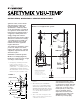
This instruction sheet shows rough-in
dimensions for Models 4-5000VT(X),
1-1000VT(X) and 1-2100VT(X). See
separate drawings enclosed with
numbered models for applicable
rough-in dimensions.
Tools required for installation of this
product are: Phillips screw driver,
tubing cutter, teflon tape, soldering
equipment, adjustable wrench and
channel-lock pliers.
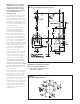
Installation of Shower System
Model 1-1000VT(X) (Figure 2)
Install HOT on left and COLD on right
according to valve markings.
1. Install piping and fittings with valve
body as shown in Figure 2 or 3.
IMPORTANT: Valve rough-in is 2-1/2”
(64mm) min. — 3” (76mm) max. from
CENTERLINE OF SUPPLIES TO FACE
OF FINISH WALL. Install so that surface
indicated on plaster shield on valve
is flush with finish wall as shown in
Figure 1.
2. When finishing tile wall REMOVE
(pull off; don’t turn) ENTIRE PROTEC-
TIVE PLASTER SHIELD and FILL AREA
AROUND VALVE BODY WITH GROUT
OR PLASTER. DO NOT PLASTER OVER
SC-2 CAP OR SERVICE STOPS IF SO
EQUIPPED.
3. Turn on hot and cold supplies, valve
will not operate unless both hot and
cold water are turned on.
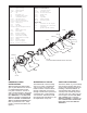
4. This valve is equipped with a limit
stop screw to be used to limit
valve handle from being turned
to excessively hot water discharge
temperatures. To adjust, remove
dome cover (SC-13/18), place
handle (VT-112) on stem, open
valve to maximum desired
temperature and turn in limit
stop screw (SC-26) until it seats.
WARNING: Failure to adjust
the limit stop screw properly
finish wall face
2
3" 76mm max.
64mm min.
1
2
''
supplies
C
L
plaster shield
4
1
4
''- 4 "
108mm
114mm
1
2
FIGURE 2
Model 1-1000VT(X) Shower System
FIGURE 1
All floor to center dimensions optional. Concealed piping and fittings not furnished by manufacturer.