
Installation Guide

4ZV-3247 REV 0
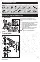
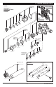
4. DETERMINE WALL TYPE
4.1 T-176 Protective Shield 4.2 T-177 Valve Mounting Plate
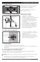
4.3 Drywall or Other Type Wall
Protective shield (T-176) is required for drywall,
plaster or other type walls with:
• 1/2 inch (13 mm) or greater wall thickness
1. Attach protective shield by snap fitting over
end of valve spindle to protect valve during
wall construction.
2. Finished wall must be flush with back side
of protective shield surface.
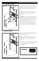
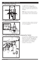
4.4 Thin Wall Installation
Valve mounting plate (T-177) is required for
fiberglass or acrylic walls, and optional for
plaster or other type walls with:
• Minimum 1/16 inch (2 mm) wall thickness
• Maximum 1/2 inch (13 mm) wall thickness
1. Seat mounting plate against valve (see
FIGURE 4.2 for orientation).
2. Valve mounting plate must be flush with
inner wall.
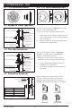
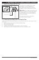
4.5 Alternative Rough-ins
When installing valve used with any of the
shower or tub/shower trims shown below,
reference rough-in dimensions as shown in
FIGURE 4.5 instead of standard valve rough-in:
-
F
I
N
I
S
H
E
D
W
A
L
L
M
U
S
T
B
E
F
L
U
S
H
W
I
T
H
B
O
T
T
O
M
O
F
T
H
I
S
S
U
R
F
A
C
E
I
M
P
O
R
T
A
N
T
FIGURE 4.1
Without service stops
FIGURE 4.2
With service stops
Wall Cutout Hole Size
3-1/2" (89 mm) min
4" (102 mm) max
1/2" (13 mm) or greater
Rough-in
2-3/8"
± 1/2"
(60 mm ± 13 mm)
pipe centerline
to front of
finished wall
finished wall
protective shield
hot & cold
supply inlets
tub spout
supply
shower supply
FIGURE 4.3
Wall Cutout Hole Size
3-1/2" (89 mm) min
4" (102 mm) max
1/16" (2 mm) min
1/2" (13 mm) max
finished wall
valve mounting plate
Rough-in
2-3/8"
± 1/2"
(60 mm ± 13 mm)
pipe centerline
to front of
finished wall
hot & cold
supply inlets
tub spout
supply
shower supply
FIGURE 4.4
Oxford
Canterbury
Carrington
Temptrol
Commercial
Rough-in
2" (51 mm)
± see table
pipe centerline
to finished wall
finished wall
Trim Series ± Tolerance
Oxford
Canterbury
Carrington
Temp Com
± 1/4" (± 6 mm)
± 1/2" (± 13 mm)
± 1/2" (± 13 mm)
± 1/2" (± 13 mm)
FIGURE 4.5