
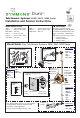
Installation Guide

Page 2
Installation Instructions
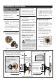
5) Remove protective shield
If protective shield was attached
in Step 3 then remove shield
snap tted over the end of valve
spindle once valve is securely
installed and wall nish work
has been completed.
6) Adjust valve packing nut
Reference gure 3 below
■ Turn hot & cold supplies on.
Valve will not operate unless
both hot and cold water supply
pressures are turned on.
■ Place handle over end of control
spindle stem.
■ Adjust packing nut for positive
frictional resistance as handle
is rotated from shuto position
across adjustment range.
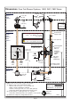
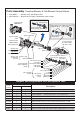
Rough-in Installation
Control valve assembly, piping
and fittings (Note: Illustrations below
show valve model without stops)
Reference as required: Page
Visual guide ....................................1
Dimensions illustration ................4
1) Determine wall thickness
■
Determine type of wall and wall
thickness where valve will be
mounted.
■ Consider whether to use mounting
plate by reviewing gure 2 below.
■ Skip ahead to Step 3 if mounting
plate is not used.
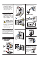
2) Attach valve mounting plate
Seat mounting plate against valve
assembly as illustrated in gure 1.
3) Attach protective shield
■ Reference gure 2 to determine
whether shield is required.
■ Attach protective shield by snap
tting over end of valve spindle.
4) Install piping, fittings and
control valve
Piping and ttings not supplied
■ Control Valve
Install through cutout hole in wall
as specied in gure 2 below and
dimension illustration on page 4.
■ Showerhead (S on valve)
Pipe from outlet port on valve
marked S to showerhead
mounting arm location.
■ Hot & Cold Supply (H & C)
Pipe hot water supply to valve
inlet marked H and cold water
supply to valve inlet marked C.
■ Tub Spout (T on valve)
Pipe from outlet port on valve
marked T to tub spout.
Important! Do not
substitute Tub Spout with
restrictive ttings such as
PEX, CPVC or outlet accessories such
as a ledge spout, hose and spray that
would subject the valve to excessive
internal back pressure, otherwise
operation will be compromised.
Figure 1 Mounting plate
Figure 3 Valve adjustments
Figure 2 Mounting valve
wall
Temp Limit
stop screw
packing nut
control
spindle
stem
p/n T-176
p/n T-177
Protective shield
When mounting plate is used,
then shield is optional for
protecting end of valve during
installation.
"snap on-off"
wall cutout hole size
3-1/2" (89 mm) min
4" (102 mm) max
nished
wall
Ensure valve’s
mounting plate
is ush against
inner wall
Walls for using T-177 valve mounting plate
Fiberglass or acrylic walls (required)
Plaster or other type walls (optional)
1/16" (2 mm) min 1/2" (13 mm) max
wall cutout hole size
3-1/2" (89 mm) min
4" (102 mm) max
Finished wall must be
ush with back side of
protective shield surface
nished wall
Dry wall, plaster or other type wall
1/2" (13 mm) or greater
Protective shield
"snap on-off"
(required when
valve mounting
plate is not used)
2-3/8"
±
1/2"
(60 mm
±
13 mm)
pipe centerline
to nished wall