
Installation Sheet
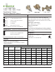

10
Operation & Adjustment
Cycle valve to full hot (counterclockwise) then cold
(clockwise) 3 full times allowing valve to reach full
temperature. With approximately 80% of the design
intent owing water, turn adjustment bolt to obtain
desired setting and lock nut in place. Thermostatic
water controllers should be sized according to the ow
capacity required from the valve, NOT the pipe size sup-
plied to the valve. For assistance and technical support
in sizing and selection of the proper TEMPCONTROL
Thermostatic Water Controller, consult the Symmons
TEMPSIZE™ computer sizing software, your local repre-
sentative or Symmons Customer Service Department at
1-800-SYMMONS.
Maintenance
The cartridge unit contains the entire valve control
mechanism. For non-interrupted service, keep a spare
cartridge on hand.
TempControl valve control mechanism must be kept
clean and free from deposits and any foreign matter
build-up that will be present in many water systems.
Inspect within 30 days of initial installation or opera-
tion. If inspection determines that your water system
causes deposits and foreign matter build-up month-
ly, then valve should be cleaned monthly as follows:
Remove cartridge (see page 11 for Cartridge Removal
& Replacement section) and soak in any acceptable
de-liming agent (or regular household vinegar). Wash off
deposits, be sure piston is moving freely in its sleeve,
and replace cartridge. Clean more frequently if your
system so demands (do not completely remove piston
from cartridge).
The Check Valves in the TempControl are highly important
factors in its proper operation. If chips, dirt or other foreign
materials lodge on the seats and prevent the checks from
fully seating, there may be a bypass of water into the
opposing line, and the TempControl will not operate to
its set delivery temperature. A bypass may be detected
by feeling the supply line while the TempControl is not
operating. If, for example, the cold line feels hot, the cold
water check is not seating properly. It should be removed
and the check and its seat cleaned.
CAUTION: Turning adjustment bolt fully counter-
clockwise will remove bolt from TempControl. If
this occurs simply replace bolt.
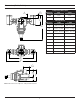
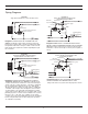
For systems piped to Diagram 4:
Follow Steps 2 through 9 for systems piped to
Diagram 3. Ignore reference to recirculating pump in
Step 9 (not applicable to this installation).
Operation & Maintenance
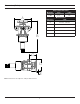
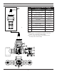
For systems piped to Diagram 2:
1. With ball valve closed, set TempControl to desired
temperature with water owing from tempered water
line.
2. After obtaining desired temperature, stop the water
ow.
3. Crack the ball valve open so that a small amount of
water is returned to the hot water source. This allows
the TempControl to maintain the set temperature
during periods of no draw on the system.
4. During no draw, observe the thermometer on the
discharge of the TempControl. If the temperature
increases above the setting in Step 1, close the ball
valve slightly or if temperature decreases, open it
slightly.
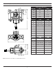
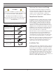
For systems piped to Diagram 3:
1. Turn off recirculating pump and close ball valve.
2. Shut off (V1).
3. Open 5 showers or equivalent to the full hot position.
4. Set small TempControl valve (TMV2) to the full cold
position and note the temperature on thermometer.
5. Shut off valve (V2) and open valve (V1). Set large
TempControl valve (TMV1) to desired system tem-
perature (make sure adjustment screw on PRV valve
is in the full clockwise position).
6. Shut off 2 showers or equivalent (leaving 3 still on)
and open valve (V2).
7. Turn PRV adjustment screw counterclockwise until
temperature (T) equals that obtained in Step #4.
8. Adjust TempControl valve (TMV2) to desired system
temperature and system will be in operational mode.
9. Stop the water ow, after obtaining desired tempera-
ture and turn on the recirculating pump.
Crack the ball valve open so that a small amount of
water is returned to the hot water source. This allows
the TempControl to maintain the set temperature
during periods of no draw on the system.
During no draw, observe the thermometer on the
discharge on the TempControl. If the temperature
increases above the setting in Step #8, close the ball
valve slightly or open it if the temperature decreases.
10.
11.