
Installation Guide


Installation
Caution: Be sure to turn off hot and cold water supplies
before installing or servicing faucet.
1. Loosely install the anchor bar (KN-23), spacer (KN-26) and
nut (L-36) on the mounting bolts and place gasket on base
of faucet. Push faucet supplies and anchor bolt/spacer/nut
assemblies with gasket through holes in sink. Secure faucet
to sink by tightening nuts from underside. (If sink or coun-
ter surface is uneven, use putty or sealant to make proper
seal under base.)
2. Connect hot supply to le tube and cold supply to right
tube using appropriate connectors.
3. Pop-up drain installation:
a) Remove pop-up plug, tail piece and ange from the drain
body. Make sure that locknut is threaded all the way
down onto the body with at friction washer in middle
and beveled washer on top.
b) Apply plumbers putty or sealant to bottom of ange.
c) Install drain body through drain opening in lavatory
and screw ange onto the drain body making sure that
the threads are completely engaged for proper sealing
and strength of the connection. Apply joint compound
to all threaded parts to insure proper seal. Apply putty or
teon tape to tail piece before attaching to drain body.
d) Tighten locknut to compress the beveled ange evenly
across the bottom of the drain opening taking care not to
over tighten the locknut, causing damage to the lavatory.
e) Remove one of two ball washers from inside the
threaded cavity. Insert pop-up plug and pivot rod into
body. Add one ball washer (the second ball washer
should remain inside the body) to the outside of the ball.
Tighten the retaining nut until the ball is seated on the
internal and external ball washers.
Note: e pop-up plug can be installed either in the remov-
able or non-removable position, depending on the location
of the hole located in the guide at the bottom of the plug.
f) Slide the pivot rod through one side of the spring clip,
then the appropriate adjustment hole and then other
side of the spring clip.
g) Insert li rod through faucet housing and the top of the
li strap and secure it in place by tightening the screw.
Note: To ensure proper operation of li rod and pop-
up, some adjustment of the linkage may be required.
ere are two possible adjustment points: 1) li strap to
li rod and 2) li strap to pivot rod.
4. It is very important to thoroughly ush the supply lines to
prevent foreign matter, i.e. copper chips, sand, stones, etc.
from damaging the sealing surfaces of cartridge.
Remove aerator and turn valve handle on to full cold posi-
tion, open cold supply. Without closing, turn handle to full
hot and open hot supply. Let water run in hot only and cold
only positions long enough to ush supply lines thoroughly.
Shut o faucet and replace aerator. Check for leaks.
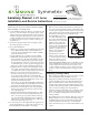
5. e handle limit stop can be
set to limit handle turn to the
hot position. e limit mecha-
nism is factory set to allow full
handle travel. To adjust the
limit stop, turn handle to the
full hot position and li handle
to open faucet approximately
half way to obtain a smooth
ow for correct initial tem-
perature measurement.
6. If when faucet is on and in
full hot position and water is
too hot, shut o water, remove
plug button (KN-157), loosen
set screw (L-22) and remove
handle (KN-3RB, KN-3BRB or LN-135). Li limit stop ring
using a small at head screw driver and rotate clockwise
to lower temperature. If water is not hot enough, rotate
counter clockwise (See Figure 1 above). Aer correct tem-
perature is achieved, reattach handle, reversing procedure
above.
Replacing cartridge (KN-4)
1. Remove plug button (KN-157), loosen set screw (L-22) and
remove handle (KN-3RB, KN-3BRB or LN-135).
2. Engage tabs in cartridge wrench (LN-34) with slots in com-
pression ring (KN-2) and use screwdriver in wrench holes or
pliers on wrench and turn counter clockwise until compres-
sion ring engages with cap (LN-8). Continue turning counter
clockwise so that cap/ring assembly is removed from the body
(LN-371). Remove cartridge and o-ring seal (KN-4).
3. Install new cartridge while taking care to maintain position
of the o-ring seal at the base of the cartridge. Match posts
in base of cartridge with alignment holes in valve body
during assembly.
4. Reassemble faucet in reverse fashion. read cap onto body
rmly by hand. Do not use a wrench which may damage
the nish. Tighten compression ring (KN-2) nger tight
using the wrench (LN-34) then 1/4 to 1/2 turn further.
5. Set hot water limit stop in accordance with installation step
5 above.
Limit stop adjust
Lavatory Faucet S-20 Series
Installation and Service Instructions
Symmetrix
®
For California Residents
WARNING: is product contains chemicals known to
the State of California to cause cancer, birth defects, or
other reproductive harm.
Figure 1