
Installation Guide

3
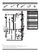
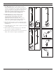
3. Parts Breakdown (Model Numbers Ending in TRMTC)
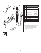
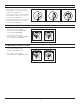
5. Installation - Adjust Packing Nut (Model Numbers Ending in TRMTC)
1) Turn hot and cold supplies on. Valve will not operate unless both hot and cold water supply pressures are on.
2) Place handle over flow control spindle.
3) Tighten packing nut for positive frictional resistance as handle is rotated from shut-o position across adjustment range.
6. Installation - Setting Limit Stop Screw (Model Numbers Ending in TRMTC)
1) Turn hot and cold supplies on. Valve will not operate unless both hot and cold water supply pressures are on.
2) Place handle on flow control spindle and open valve to maximum desired temperature.
3) Turn limit stop screw clockwise until it seats.
WARNING: Failure to adjust limit stop screw properly may result in serious scalding.
The temperature limit stop screw limits valve handle from being turned to maximum position resulting in excessive hot
water discharge temperatures.
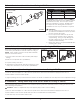
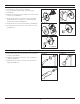
4. Installation - Remove Test Cap (Model Numbers Ending in TRMTC)
1) Check for leaks around the valve assembly and all pipe
fittings.
Flow control spindle (TA-10) and cap assembly (T-12A) will
come factory assembled for all model numbers ending in
TRMTC. When ready to remove Test Cap and install trim,
follow the instructions below:
2) Remove test cap from valve (FIGURE 4.1).
3) If system is dirty, flush valve.
4) Thread flow control spindle and cap assembly into valve
body. Turn clockwise to secure to valve (FIGURE 4.2).
FIGURE 4.1
FIGURE 4.2
LIMIT STOP
SCREW
2
1
PACKING
NUT
FIGURE 3
Replacement Parts
Item Description Part Number
1 Cap Assy. T-12A
2 Flow Control Spindle TA-10
IMPORTANT: Model numbers ending in TRMTC
coordinate with Temptrol pressure balancing valves
ordered with Test Cap. The Test Cap is used to
allow pressurization of system. Do not remove
test cap from valve during wall construction,
installation of valve or pressurization of system.
WARNINGS:
1. Test cap rated for pressure testing up to 200
psi maximum. DO NOT exceed 200 psi while
pressure testing valve body.
2. Do not expose valve with test cap to heat
for longer than 2 minutes when soldering
copper tubing. Doing so may damage the
internal components of the valve and will
void the product warranty.
3. Ensure test cap is re-torqued to 30 lb-ft after
soldering valve body.