
Installation Guide
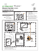


Page 2
Installation Instructions
Figure 1 Mounting plate
Rough-in Installation
Control valve assembly, piping and
fittings (Note: Illustrations below show
valve model without stops)
Reference as required: Page
Visual guide ....................................1
Dimensions illustration ................3
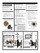
1) Determine wall thickness
■
Determine type of wall and wall thickness
where valve will be mounted.
■ Consider whether to use mounting plate
by reviewing gure 2 below.
■ Skip ahead to Step 3 if mounting plate
is not used.
2) Attach valve mounting plate
Seat mounting plate against valve
assembly as illustrated in gure 1.
3) Attach protective shield
■ Reference gure 2 to determine
whether shield is required.
■ Attach protective shield by snap tting
over end of valve spindle.
4) Install piping, fittings and
control valve
Piping and ttings not supplied
■ Control Valve
Install through cutout hole in wall
as specied in gure 2 below and
dimension illustration on page 3.
■ Showerhead (S on valve)
Pipe from outlet port on valve marked
S to showerhead mounting arm
location.
■ Hot & Cold Supply (H & C)
Pipe hot water supply to valve inlet
marked H and cold water supply to
valve inlet marked C.
■ Tub Spout (T on valve)
Pipe from outlet port on valve marked
T to tub spout.
Important! Do not substitute
Tub Spout with
restrictive
ttings such as
PEX, CPVC or
outlet accessories such as a ledge
spout, hose and spray that would
subject the valve to excessive
internal back pressure, otherwise
operation will be compromised.
5) Remove protective shield
If protective shield was attached in
Step 3 then remove shield snap tted
over the end of valve spindle once
valve is securely installed and wall
nish work has been completed.
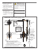
6) Adjust valve packing nut
Reference gure 3 below
■ Turn hot & cold supplies on.
Valve will not operate unless both hot
and cold water supply pressures are
turned on.
■ Place handle over end of control
spindle stem.
■ Adjust packing nut for positive
frictional resistance as handle is
rotated from shuto position across
adjustment range.
wall cutout hole size
3-1/2" (89 mm) min
4" (101 mm) max
Finished wall must be
ush with back side of
protective shield surface
nished wall
Dry wall, plaster or other type wall
1/2" (13 mm) or greater
Protective shield
"snap on-off"
(required when
mounting plate
is not used)
2-3/8"
±
1/2"
(60 mm
±
13 mm)
pipe centerline
to nished wall
wall cutout hole size
3-1/2" (95 mm) min
4" (101 mm) max
nished
wall
Ensure valve’s
mounting plate
is ush against
inner wall
Walls for using T-177 mounting plate
Fiberglass or acrylic walls (required)
Plaster or other type walls (optional)
1/16" (2 mm) min 1/2" (13 mm) max
p/n T-176
p/n T-177
Protective shield
When mounting plate is used,
then shield is optional for
protecting end of valve during
installation.
"snap on-off"
Figure 3 Valve adjustments
wall
Temp Limit
stop screw
packing nut
control
spindle
stem
Figure 2 Mounting valve