
Installation Guide


Page 3
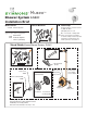
11-1/8"
(283 mm)
4-5/8"
(117 mm)
nished wall
Floor
hot / cold
supply
showerhead
supply
5/8" (16 mm)
1/2" (13 mm)
6-1/4" Diameter
(159 mm)
tub spout
supply (plugged)
1/2" (13 mm)
2-3/8"
±
1/2"
(60 mm
±
13 mm)
pipe centerline
to nished wall
*
Note (2)
1/2"-14 NPT
approx
45"
(1143 mm)
approx
32"
(813 mm)
mounting plate,
*
Notes (1)(2)
Temptrol
control valve
S-46-1-BODY
S-46-1X-BODY
2" Diameter (51 mm)
*
Notes:
(1) Walls for using T-177 mounting plate (MP)
■ Wall is 1/16" (2 mm) min • 1/2" (13 mm) max
■ Fiber or acrylic walls (MP required)
■ Plaster or other type walls 1/2" or less (MP optional)
■ Protective shield (optional)
(2) Dry wall, plaster or other type walls 1/2" or greater
■ Protective shield, snap on end of valve spindle (required)....
(3) Dimensions subject to change without notice
Dimensions Museo Shower System, S-5301
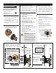
7) Flush system, check for leaks
■ Turn valve to the warm position and
run for a few minutes.
■ If system is dirty, remove valve spindle
in center of valve to ensure proper
ushing. (See service instructions.)
■ Check for leaks around valve assembly
and all pipe ttings.
8) Set Temp Limit stop screw
Reference page 2, gure 3
e temperature limit stop screw
limits valve handle from being turned
to maximum position resulting
in excessive hot water discharge
temperatures.
Warning: Failure to adjust
Temp Limit stop screw properly
may result in serious scalding.
■ Place handle on control spindle stem
and open valve to maximum desired
temperature.
■ Turn Temp Limit stop screw clockwise
until it seats.
Note:
Do not install positive shut-o
devices on control valve outlet or devices
that do not allow the valve to ow at least
1.5 gpm.