
Installation Guide
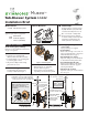

Tub-Shower System S-5302
Installation Brief
1 2 3 4
Pipe
Sealant
Plumbers
Putty
Tools & Materials
Need Help?
Contact Symmons customer service
at (800) 796-6667, (781) 848-2250,
customerservice@symmons.com
Mon - Fri 7:30 am - 7:00 pm EST
Please check Symmons website
for technical help, the latest product
information and warranty policy.
www.symmons.com/service
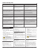
Museo™
Decorative Finish Code
append to part numbers if applicable
-STN
Satin Nickel
-BLK
Polished Graphite
--
Chrome (standard)
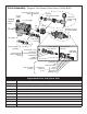
4) Install piping, fittings and
control valve
Piping and ttings not supplied
■ Control Valve
Install valve through cutout hole in
wall as specied in gure 2 below and
dimension illustration on page 2.
■ Showerhead (S on valve)
Pipe from outlet port on valve marked S
to showerhead mounting arm location.
■ Hot & Cold Supply (H & C)
Pipe hot water supply to valve input
marked H and cold water supply to
valve input marked C.
■ Tub Spout (T on valve)
Pipe from outlet port on valve marked
T to tub spout.
Rough-in Installation
Control valve, piping & fittings
Reference rough-in dimension illustration
on page 2 as required.
1) Determine wall thickness
■
Determine type of wall and wall
thickness where valve will be mounted.
■ Consider whether to use mounting plate
by reviewing gure 2 below.
■ Skip ahead to Step 3 if mounting
plate will not be used.
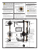
2) Attach mounting plate to valve
Seat mounting plate against valve
assembly as illustrated in gure 1.
3) Attach protective shield
■ Reference gure 2 to determine
whether shield is required.
■ Attach plastic protective shield by
snap tting over end of valve spindle.
Figure 1
Mounting plate
wall cutout hole size
3-1/2" ( 89 mm) min
4" (101 mm) max
Finished wall must be
ush with back side of
protective shield surface
nished wall
Dry wall, plaster or other type wall
1/2" (13 mm) or greater
Protective shield
"snap on-off"
(required when
mounting plate
is not used)
2-3/8"
±
1/2"
(60 mm
±
13 mm)
pipe centerline
to nished wall
wall cutout hole size
3-1/2" ( 95 mm) min
4" (101 mm) max
nished
wall
Ensure valve’s
mounting plate
is ush against
inner wall
Walls for using T-177 mounting plate
Fiberglass or acrylic walls (required)
Plaster or other type walls (optional)
1/16" (2 mm) min 1/2" (13 mm) max
p/n T-176
p/n T-177
Protective shield
When mounting plate is used,
then shield is optional for
protecting end of valve during
installation.
"snap on-off"
Figure 2 Mounting valve
Model Number
S-5302
Tub-Shower System