
Installation Guide
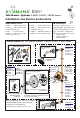

Page 4
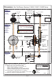
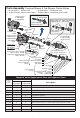
12"
(305 mm)
4-7/8"
(124 mm)
nished wall
Floor
HOT / COLD
supply inlets
showerhead
supply
5/8" (16 mm)
7-1/2" dia
(191 mm)
2-1/2" dia
(64 mm)
1/2"-14 NPT
1/2"-14 NPT
mounting plate
p/n T-177
*
Note (1)
Temptrol
control
valve
*
Notes: (also reference page 2, figure 2 for details)
(1) Walls for using T-177 mounting plate (MP)
■ Wall is 1/16" (2 mm) min • 1/2" (13 mm) max
■ Fiber or acrylic walls (MP is required)
■ Plaster or other type walls 1/2" or less (MP optional)
■ Protective shield usage (optional for protection only)
(2) Dry wall, plaster or other type walls 1/2" or greater
■ Protective shield attached to valve spindle to locate position
(3) Dimensions subject to change without notice
Wall cutout hole size
3-1/2" (89 mm) min
4" (101 mm) max
Finished wall to rear of valve
3-1/2"
±
1/2" (89 mm
±
13 mm)
Finished wall to pipe centerline
2-3/8"
±
1/2" (60 mm
±
13 mm)
*see note (2)
Protective
shield
p/n T-176
5-7/8"
(149 mm)
2-3/4"
(70 mm)
2-5/8" dia
(68 mm)
approximately
Shower only = 42" (1067 mm)
Tub-Shower = 32" (813 mm)
Model Series
S-5500
S-5500-X
S-5500TS
S-5500TS-X
S-5501
S-5501-X
S-5502
S-5502-X
tub spout
supply or
supply plug
COLD
supply
inlet
Model Series
S-5502
S-5502-X
Model Series
S-5501
S-5501-X
S-5502
S-5502-X
HOT
supply
inlet
approx
77"
(1956 mm)
4-3/8"
(111 mm)
3-1/2
±
½"
(89 mm)
(
±
13 mm)
6-1/8 ± 1/2"
(157 ±13 mm)
Dimensions Elm Tub-Shower Systems, S-5500, S-5501, S-5502 Series