
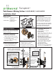
Installation Guide

Page 2
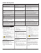
■ Tighten packing nut for positive
frictional resistance as handle is
rotated from shuto position across
adjustment range.
7) Flush system and check for leaks
■ Turn valve to the warm position and
run for a few minutes.
■ If system is dirty, remove valve spindle
in center of valve to ensure proper
ushing. (See service instructions.)
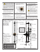
Figure 3 Valve adjustments
wall
Temp Limit
stop screw
packing nut
control
spindle
stem
Important! Do not substitute
Tub Spout with restrictive
ttings such as PEX, CPVC or
outlet accessories such as a ledge
spout, hose and spray
that would
subject the valve excessive internal back
pressure, otherwise operation will be
compromised.
5) Remove protective shield
If attached in Step 3, then remove shield
snap tted over the end of valve spindle
once valve is securely installed and wall
nish work has been completed.
6) Adjust valve packing nut
Reference gure 3
■ Turn hot & cold supplies on.
Valve will not operate unless both hot
and cold water supply pressures are on.
■ Place handle over control spindle stem.
■ Check for leaks around valve
assembly and all pipe ttings.
8) Set Temp Limit stop screw
Reference gure 3
e limit stop screw limits valve handle
from being turned to maximum
position resulting in excessive hot
water discharge temperatures.
Warning:
Failure to adjust
limit stop screw properly may
result in serious scalding.
■ Place handle on control spindle and open
valve to maximum desired temperature.
■ Turn limit stop screw clockwise until
it seats.
Note:
Do not install positive shut-o
devices on control valve outlet or devices that
do not allow the valve to ow at least 1.5 gpm.
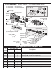
hot / cold supply
shower supply
tub spout supply
(S-4002-BODY)
showerhead supply
5/8" (16 mm)
1/2" (13 mm)
2-5/8" (67 mm)
1/4" (6 mm)
tub spout
supply
supply plug
(S-4001-BODY)
Notes:
(1) Dimensions subject to
change without notice.
(2) Valve spindle can be further
extended through thicker
walls when mounting plate
is not used.
(3) Dimension applies when
T-177 mounting plate is
not used.
(4) Use alternate dimension
gures when installing
escutcheon trim listed in
table below.
Temptrol
mixing valve
Tub-Shower Valve
S-4002-BODY
Shower Valve
S-4001-BODY
2-3/8"
±
1/2"
(60 mm
±
13 mm)
pipe centerline
to nished wall
See Notes 3 & 4
Trim Series Pipe centerline to nished wall
Oxford 2" (51 mm)
±
1/4" (
±
6 mm)
Allura
*
2" (51 mm)
±
1/2" (
±
13 mm)
Carrington 2" (51 mm)
±
1/2" (
±
13 mm)
Canterbury 2" (51 mm)
±
1/2" (
±
13 mm)
Temp Com 2" (51 mm)
±
1/2" (
±
13 mm)
*
with standard LHM handle only
approx.
45"
(1143 mm)
approx.
32"
(813 mm)
12"
(305 mm)
nished wall
Floor
wall
Rough-in Dimensions Temptrol Shower & Tub-Shower Mixing Valves