
Installation Sheet

2
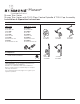
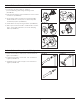
1. Recommended Tools
CC
A
G
G
I
I
J
J
K
K
F
F
B
B
D
D
H
H
L
L
M
M
N
N
Q
Q
P
P
O
O
E
E
Floor
Floor
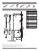
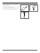
FIGURE 2
Notes:
1) Valve body and piping not included and shown as reference only.
2) Plaster shield (p/n T-176) for dry wall, plaster or other type walls 1/2" or greater.
3) All dimensions measured from nominal rough-in (see N as reference).
4) Dimensions subject to change without notice.
Phillips Screwdriver
Adjustable Wrench
Safety Glasses Thread Seal TapeDrill
Allen Wrench (3mm)
FIGURE 1
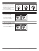
2. Dimensions
Measurements
A Ø 2", 51 mm
B 11-1/8", 283 mm
C Ø 2", 51 mm
D
Male 1/2" IPS thread
must protrude 3/8"
from finished wall
E 6", 152 mm
F 77", 1956 mm
G Ø 6-1/4", 159 mm
H 3-1/2", 89 mm
I Ø 2-1/4", 57 mm
J
Trim with tub spout:
Ref. 32", 813 mm
Trim without tub spout:
Ref. 42", 1067 mm
K Ref. 12", 305 mm
L 3-1/4", 83 mm
M 3-3/4", 95 mm
N
(Rough in)
2-3/8" ± 1/2", 60 mm ± 13 mm
O 1/2" - 14 NPT
P 1/2", 13 mm
Q 7-1/8", 181 mm