
Installation Sheet

INSTALLATION OF:
SHOWER SYSTEMS AND
TUB/SHOWER SYSTEMS
Tools required for installation of this product
are: Phillips screw driver, tubing cutter,
teflon tape, soldering equipment, adjustable
wrench and channel-lock pliers.
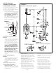
1. Install piping and fittings with valve body
as shown in Figure 2 or 3. IMPORTANT:
Valve rough-in is 2-3/8” +/- 1/2”
from CENTERLINE OF SUPPLIES TO
FACE OF FINISH WALL. Install so that
line indicated on rough-in plaster shield
(T-176) on valve is flush with finish wall
as shown in Figure 1 (See Figure 5 for
fiberglass wall installation).
Tub/Shower System (Figure 2)
Model A
Pipe shower head from outlet marked
“S” and to tub spout from outlet marked
“T”. The diverter mechanism in this
valve is designed so that it cannot be
subject to any back pressure, other than
is imposed by the spout supplied with
this package. DO NOT SUBSTITUTE
OTHER OUTLET ACCESSORIES FOR
THE TUB SPOUT (SUCH AS HOSE
AND SPRAY, SHOWER HEAD, BODY
SPRAY, LEDGE SPOUTS, ETC.) OR
ANY PIPE ADAPTER OR ADDITIONAL
FITTINGS (SUCH AS PEX, ETC.)
THAT CAN CAUSE BACK PRESSURE
THROUGH THE VALVE. Install HOT on
left and COLD on right according to valve
markings.
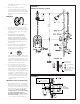
Shower System (Figure 3)
Model B
Pipe to shower head from outlet marked
“S”. DO NOT REMOVE PLUG FROM
OUTLET MARKED “T”. Install HOT on left
and COLD on right according to valve
markings.
Tub/Shower, Shower or Tub
System (Figure 2A) Model C
Tub/Shower System: The valve in this
system has a built-in choke for use with a
diverter spout. Follow piping instructions
for Model A valve.
nish wall face
4" (101mm) Max
2
3
8
''
60mm
1
2
''
supplies
C
L
+
3" (75mm) Min
plaster shield
(T-176)
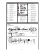
FIGURE 1
Shower System: Pipe shower head
from outlet marked “S”. Install either the
included copper sweat or 1/2”-14 NPT
plug (pipe sealer required) into the outlet
marked “T” (see figure 3A).
Tub only System: Pipe tub spout from
outlet marked “T”. Install either the
included copper sweat or 1/2”-14 NPT
plug (pipe sealer required) into the outlet
marked “S” (figure 3A).
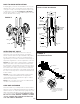
2. When finishing tile wall PULL OFF
ENTIRE PROTECTIVE PLASTER SHIELD
(T-176). If finish wall obstructs removal
of plaster shield, break off outer edge
along perforations (if necessary, carefully
use sharp blade to facilitate removal).
After plaster shield is removed FILL AREA
AROUND VALVE BODY WITH GROUT OR
PLASTER.
3. TURN ON HOT AND COLD SUPPLIES,
valve will not operate unless both hot
and cold water are turned on.
4. Unscrew dome cover (T-19/20) and
tighten packing nut (T-17) for positive
frictional resistance to handle turn
throughout adjustment cycle and at shut-
off position. Check valve cap, packing
nut, diverter spindle o-ring and all valve,
pipe and fitting connections for leaks.
5. SET LIMIT STOP SCREW AS DIRECTED
AFTER “IMPORTANT” IN BOLD TYPE ON
approx.
44 7/8"
1140mm
4 7/8"
124mm
6 3/8"
162mm
FIGURE 2
Model A: Tub/Shower System
FIGURE 2A
Model C: Diverter spout installation
Page 2