
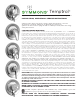
Installation Sheet

TROUBLE SHOOTING CHART
Problem Cause Solution (Follow service instructions)
Valve will not pass water. Hot and cold water not turned on. Turn on both supplies. Valve will not operate
unless both HOT and COLD water pressure is
turned on.
Valve leaks when shut off. Hot and cold washers are worn, or foreign
matter (solder, chips, etc.) are between washers
and seat surfaces
Replace Hot and Cold washers, inspect top
surface on hot and cold seats and replace if
necessary.
Temperature control handle is turned from
cold to hot (or hot back to cold) and volume
from spout or head is not constant.
Pressure balancing piston housed in spindle
assembly is blocked from free movement by
foreign matter.
With valve open half way, remove handle and
tap spindle with plastic hammer. If problem
not solved, remove spindle assembly com-
pletely and tap handle against solid object to
free piston. Soaking in household vinegar will
help free foreign matter.
Valve delivers sufcient quantity of cold, but
little hot, or the reverse of this.
Same as above Same as above
Temperature varies without moving handle. Same as above Same as above
Valve delivery temperature reduces gradually
during use; must be turned on to hotter posi-
tions to maintain constant temperature.
Overdraw on hot water supply, i.e., running
out of hot water.
Reduce maximum ow by using volume
control adjustment on valve or shower head.
This will allow longer period of use before
overdrawing hot water supply.
Valve delivers hot water when initially opened
and water turns colder when the handle is
rotated in a counter-clockwise direction.
Valve is piped incorrectly, i.e., the hot supply is
piped to the cold inlet to the valve and the cold
supply is piped to the hot inlet of the valve.
If piping is accessible, correct piping connec-
tions to the valve. If piping is not accessible,
contact factory to order a reverse seat and
tool (T-108 KIT). Older installations may require
replacement of the hot seat (T-1) as well
In tub/shower valves, when diverter is set in
shower position a trickle of water runs from
tub spout.
A design function of this valve is to allow
a trickle of water from the tub spout when
diverter is set for shower position, This trickle of
water is necessary to ensure safe operation in
that the valve will be shut off at main handle
and NOT with diverter handle.
9/03
TROUBLESHOOTING CHART
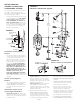
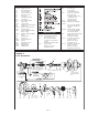
1. Shut off water supply to valve.
2. Remove handle plug button (T-33) and
handle (T-31).
3. Remove dial [T-29(A,B,C)] and escutch-
eon (T-27) by removing escutcheon
screws (T-28). Remove all remaining trim.
4. Open valve to about warm position
and unscrew cap (T-12A). Warning:
Failure to do this will damage cap and
spindle. Spindle assembly (TA-10) will
be removed with cap. Leave packing
nut (T-17) in place while unscrewing
cap to avoid distortion.
5. Ordinary service to eliminate drip-
ping or not shutting off requires only
the replacement of parts supplied in
washer and gasket kit (TA-9). Hold
spindle with (T3-31) handle while
removing hot washer screw and cold
washer retainer (remove retainer with
channel lock pliers).
6. Inspect top surfaces of hot and cold
seats and replace if necessary. Impor-
tant: When replacing hot and cold
seats, always replace both seats. Even if
only one seat appears worn, both seats
must be replaced. Use part No. (TA-4).
After long years of service, if spindle
is very loose in cold seat, replace with
part no. (TA-4). Use seat removal tool
[T-35(A,B)] for removal and replace-
ment of (TA-4). If seats are difcult
to remove and tool shifts damaging
notches, relocate tool in second posi-
tion of notches. Tighten both seats to
15 foot pounds of torque.
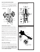
7. The perforated end of the (TA-10)
spindle assembly houses the balancing
piston which is the heart of this pres-
sure balancing valve. The piston should
be free to move back and forth and
should click when the spindle assembly
is shaken. If deposits block this action,
tap the handle end of the spindle
against a solid object to free the piston.
Soaking in household vinegar will
help free foreign matter. If this does
not free piston, replace (TA-10) spindle
assembly. DO NOT TAMPER WITH
PERFORATED CYLINDER ON THE
SPINDLE ASSEMBLY OR ATTEMPT
REMOVAL OF THE PISTON.
8. Reassemble, reversing above pro-
cedure, be sure spindle assembly is
drawn close to the cap before screw-
ing cap back into valve. WARNING:
FAILURE TO DO THIS WILL DAMAGE
CAP AND SPINDLE.
9. USE ONLY SYMMONS GENUINE REPAIR
PARTS. FAILURE TO DO SO WILL VOID
ALL WARRANTIES AND IMPAIR PROPER
OPERATION OF YOUR VALVE.
TEMPTROL
®
SERIES SERVICE INSTRUCTIONS
Problem Cause Solution (Follow service instructions)
Valve will not pass water. Hot and cold water not turned on. Turn on both supplies. Valve will not operate
unless both HOT and COLD water pressure is
turned on.
Valve leaks when shut off. Hot and cold washers are worn, or foreign
matter (solder, chips, etc.) are between washers
and seat surfaces
Replace Hot and Cold washers, inspect top
surface on hot and cold seats and replace if
necessary.
Temperature control handle is turned from
cold to hot (or hot back to cold) and volume
from spout or head is not constant.
Pressure balancing piston housed in spindle
assembly is blocked from free movement by
foreign matter.
With valve open half way, remove handle and
tap spindle with plastic hammer. If problem
not solved, remove spindle assembly com-
pletely and tap handle against solid object to
free piston. Soaking in household vinegar will
help free foreign matter.
Valve delivers sufcient quantity of cold, but
little hot, or the reverse of this.
Same as above Same as above
Temperature varies without moving handle. Same as above Same as above
Valve delivery temperature reduces gradually
during use; must be turned on to hotter posi-
tions to maintain constant temperature.
Overdraw on hot water supply, i.e., running
out of hot water.
Reduce maximum ow by using volume
control adjustment on valve or shower head.
This will allow longer period of use before
overdrawing hot water supply.
Valve delivers hot water when initially opened
and water turns colder when the handle is
rotated in a counter-clockwise direction.
Valve is piped incorrectly, i.e., the hot supply is
piped to the cold inlet to the valve and the cold
supply is piped to the hot inlet of the valve.
If piping is accessible, correct piping connec-
tions to the valve. If piping is not accessible,
contact factory to order a reverse seat and
tool (T-108 KIT). Older installations may require
replacement of the hot seat (T-1) as well
In tub/shower valves, when diverter is set in
shower position a trickle of water runs from
tub spout.
A design function of this valve is to allow
a trickle of water from the tub spout when
diverter is set for shower position, This trickle of
water is necessary to ensure safe operation in
that the valve will be shut off at main handle
and NOT with diverter handle.
9/03
TROUBLESHOOTING CHART
1. Shut off water supply to valve.
2. Remove handle plug button (T-33) and
handle (T-31).
3. Remove dial [T-29(A,B,C)] and escutch-
eon (T-27) by removing escutcheon
screws (T-28). Remove all remaining trim.
4. Open valve to about warm position
and unscrew cap (T-12A). Warning:
Failure to do this will damage cap and
spindle. Spindle assembly (TA-10) will
be removed with cap. Leave packing
nut (T-17) in place while unscrewing
cap to avoid distortion.
5. Ordinary service to eliminate drip-
ping or not shutting off requires only
the replacement of parts supplied in
washer and gasket kit (TA-9). Hold
spindle with (T3-31) handle while
removing hot washer screw and cold
washer retainer (remove retainer with
channel lock pliers).
6. Inspect top surfaces of hot and cold
seats and replace if necessary. Impor-
tant: When replacing hot and cold
seats, always replace both seats. Even if
only one seat appears worn, both seats
must be replaced. Use part No. (TA-4).
After long years of service, if spindle
is very loose in cold seat, replace with
part no. (TA-4). Use seat removal tool
[T-35(A,B)] for removal and replace-
ment of (TA-4). If seats are difcult
to remove and tool shifts damaging
notches, relocate tool in second posi-
tion of notches. Tighten both seats to
15 foot pounds of torque.
7. The perforated end of the (TA-10)
spindle assembly houses the balancing
piston which is the heart of this pres-
sure balancing valve. The piston should
be free to move back and forth and
should click when the spindle assembly
is shaken. If deposits block this action,
tap the handle end of the spindle
against a solid object to free the piston.
Soaking in household vinegar will
help free foreign matter. If this does
not free piston, replace (TA-10) spindle
assembly. DO NOT TAMPER WITH
PERFORATED CYLINDER ON THE
SPINDLE ASSEMBLY OR ATTEMPT
REMOVAL OF THE PISTON.
8. Reassemble, reversing above pro-
cedure, be sure spindle assembly is
drawn close to the cap before screw-
ing cap back into valve. WARNING:
FAILURE TO DO THIS WILL DAMAGE
CAP AND SPINDLE.
9. USE ONLY SYMMONS GENUINE REPAIR
PARTS. FAILURE TO DO SO WILL VOID
ALL WARRANTIES AND IMPAIR PROPER
OPERATION OF YOUR VALVE.
TEMPTROL
®
SERIES SERVICE INSTRUCTIONS
SERVICE
Symmons Industries, Inc. ■ 31 Brooks Drive ■ Braintree, MA 02184
(800) 796-6667, (781) 848-2250
■ Fax (800) 961-9621, (781) 843-3849
Website: www.symmons.com
■ Email: customerservice@symmons.com
© 2008 Symmons Industries, Inc. Printed in U.S.A.
■ ZV-89 ■ 071311