BASE INSTALLATION MANUAL - FOR CORNER SHOWER MANUEL D’INSTALLATION DE LA BASE - POUR DOUCHE EN COIN MANUAL DE INSTALACIÓN DEL PLATO - PARA LA DUCHA EN MONEDA INSTALLATION WITH A TILE WALL START WITH THIS INSTALLATION MANUAL 1) FIRST, INSTALL YOUR SHOWER BASE (USING THIS MANUAL) 2) SECOND, INSTALL YOUR SHOWER DOOR. INSTALLATION AVEC UN MUR EN TUILE COMMENCER PAR CE MANUEL D’INSTALLATION 1) PREMIÈREMENT, INSTALLEZ VOTRE BASE DE DOUCHE (EN VOUS SERVANT DE CE MANUEL).
BASE INSTALLATION: OVERVIEW INSTALLATION DE LA BASE: UN APERÇU INSTALACIÓN DEL PLATO: VISIÓN GENERAL 1. Before you start the installation of your product consult the illustration 1 below showing a side-view of the completed installation. 2. Illustration 2 shows the recommended wall structure and measurements for the product installation. NOTE: Customer must follow and comply with the local and national building and plumbing codes.
SHOWER BASE DIMENSIONS DIMENSIONS DE LA BASE DOUCHE DIMENSIONES DEL PLATO DE DUCHA Measurements Mesures 32” 34” 36” Medidas 38” A Flange width Largeur de la bride Ancho de brida B Shower base height (With flange) Hauteur de la base de douche (Avec bride) Altura de la base de la ducha (Con brida) C Threshold height (Without flange) Hauteur du seuil (Sans la bride) Altura umbral (Sin brida) D Overall shower base width Largeur totale de la base Ancho total del plato de ducha A 32 1/16" 815mm 34
PART LIST LISTE DES PIÈCES LISTA DE PIEZAS BB A CODE PART # DESCRIPTION QUANTITY # DE PIÈCE DESCRIPTION QUANTITÉ CODE PARTE # DESCRIPCIÓN CANTIDAD CÓDIO A Shower base Base de douche Plato de ducha 1 BB Screw (ST4x30mm) Vis (ST4x30mm) Tornillo (ST4x30mm) 8+1 TOOLS REQUIRED (not supplied) OUTILS REQUIS (non fournis) HERRAMIENTAS NECESARIAS (no incluido) Pencil Crayon Lápiz Saw Scie Sierra Screwdriver Tournevis Destornillador Measuring Tape Ruban à mesurer Cinta medidora Drill and dri
SAFETY INFORMATION INFORMATION SUR LA SÉCURITÉ INFORMACIÓN DE SEGURIDAD CAUTION Please carefully read the following important safety information before handling or installing this shower. There is a risk of serious injury while handling this product. To minimize these risks, please note: • • • • • • • • • • • • • Always wear safety glasses and gloves while handling. Always read and follow all the steps in the installation instructions. Inspect all contents and glass for damage before installation.
SAFETY NOTICE AVIS DE SÉCURITÉ AVISOS DE SEGURIDAD NOTICE Any modification or alteration from what is specified in this instruction manual will void any and all warranty on this product. The distributor is not responsible for any damage to the unit or personal property caused by improper installation. If you disregard instructional warnings, you will void your warranty and possibly deal with water damage.
BASE INSTALLATION INSTALLATION DE LA BASE INSTALACIÓN DEL PLATO 1 1.1. Ensure that the wall structure is leveled. 1.2. Place the shower base (A) on the floor and mark the outline using a pencil. 1.1. Assurez-vous que la structure du mur soit nivelée. 1.2. Placez la base de douche (A) sur le sol et marquez le contour à l’aide d’un crayon. 1.1. Asegúrese de que la estructura de la pared esté nivelada. 1.2. Coloque la base de la ducha (A) en el piso y marque el contorno con un lápiz. 1.
BASE INSTALLATION: SHOWER DRAIN GUIDELINES INSTALLATION DE LA BASE: DRAIN DE DOUCHE INSTALACIÓN DEL PLATO: DESAGÜE DE LA DUCHA 2 2.1. Ensure that the waste pipe plumbing is completed. 2.2. The shower drain is not supplied, these illustrations are for reference only. It is recommended that you review the drain installation from the manufacturer before continuing. Usually, the drain body must be sealed onto the waste pipe before continuing the base installation.
BASE INSTALLATION INSTALLATION DE LA BASE INSTALACIÓN DEL PLATO 3 3.1. Apply cement (2.5 to 3.8cm [1 in to 1 1/2 in] thick) within the traced contour of the shower base. This will help level the base in subsequent steps. The thickness of the cement layer varies depending on your floor. 3.2. Before setting the shower base onto the cement, it is recommended to cover the cement with a thin (2mm [1/16 in]) sheet of polyethylene.
BASE INSTALLATION INSTALLATION DE LA BASE INSTALACIÓN DEL PLATO 4 4.1. The shower base flange is slightly slopped by design. At the locations where you will screw the shower base to the studs, it is recommended that you use wood shims to fill the gap between the base flange and the studs. 4.2-4.3. Drill guide holes, and fix the shower base by screwing it to the studs. It is recommended that you screw 1 screw per stud, and aim for the center of the stud. 4.1.
BASE INSTALLATION INSTALLATION DE LA BASE INSTALACIÓN DEL PLATO 5 5.1. Cut the protruding part of the wood shims. 5.2. Let the cement dry for 24h before continuing. 5.1. Coupez la partie saillante des cales de bois. 5.2. Laissez le ciment sécher pendant 24h avant de continuer. 5.1. Cortar las cuñas de madera saliente. 5.2. Permitir que el cemento se seque durante 24 horas antes de continuar. 5.2 5.1 24H! P.
BASE INSTALLATION: DRYWALLS INSTALLATION DE LA BASE: MURS DE PLACOPLÂTRE INSTALACIÓN DEL PLATO: PANELES DE YESO 6 6.1. Ensure that the wall structure is leveled. Measure the location of the existing shower plumbing, as exemplified by the measures W1, W2, W3 and W4 below. 6.2. Before installing your drywalls, drill holes at the measured locations for the existing plumbing on the wall. Use a hole saw drill bit to neatly cut through the drywall. Also cut the drywalls the to correct height. 6.1.
BASE INSTALLATION: DRYWALLS INSTALLATION DE LA BASE: MURS DE PLACOPLÂTRE INSTALACIÓN DEL PLATO: PANELES DE YESO 7 7.1-7.2. Fix the drywalls to the studs using drywall screws. Follow the applicable building code requirements. 7.3. Note that the drywalls have to rest on top of the shower base flange, and sealed together with a bead of silicone. 7.1-7.2. Fixer les murs de placoplâtres sur les montants à l’aide de vis. Suivez les exigences du code de construction applicables. 7.3.
BASE INSTALLATION: TILE INSTALLATION DE LA BASE: TUILE INSTALACIÓN DEL PLATO: AZULEJO 8 8.1. Install the tiles on your wall. 8.2. Seal all joints with silicone. 8.1. Posez les carreaux sur votre mur. 8.2. Scellez tous les joints avec du silicone. 8.1. Instale los azulejos en su pared. 8.2. Selle todas las juntas con silicona.
BASE INSTALLATION MANUAL - FOR CORNER SHOWER MANUEL D’INSTALLATION DE LA BASE - POUR DOUCHE EN COIN MANUAL DE INSTALACIÓN DEL PLATO - PARA LA DUCHA EN MONEDA INSTALLATION WITH COMPOSITE WALL PANELS START WITH THIS INSTALLATION MANUAL 1) FIRST, INSTALL YOUR SHOWER BASE (USING THIS MANUAL) 2) SECOND, INSTALL YOUR SHOWER WALL PANELS (IF APPLICABLE). 3) THIRD, INSTALL YOUR SHOWER DOOR.
BASE INSTALLATION: OVERVIEW INSTALLATION DE LA BASE: UN APERÇU INSTALACIÓN DEL PLATO: VISIÓN GENERAL 1. Before you start the installation of your product consult the illustration 1 below showing a side-view of the completed installation. 2. Illustration 2 shows the recommended wall structure and measurements for the product installation. NOTE: Customer must follow and comply with the local and national building and plumbing codes.
SHOWER BASE DIMENSIONS DIMENSIONS DE LA BASE DOUCHE DIMENSIONES DEL PLATO DE DUCHA Measurements Mesures 32” 34” 36” Medidas 38” A Flange width Largeur de la bride Ancho de brida B Shower base height (With flange) Hauteur de la base de douche (Avec bride) Altura de la base de la ducha (Con brida) C Threshold height (Without flange) Hauteur du seuil (Sans la bride) Altura umbral (Sin brida) D Overall shower base width Largeur totale de la base Ancho total del plato de ducha A 32 1/16" 815mm 34
PART LIST LISTE DES PIÈCES LISTA DE PIEZAS BB A CODE PART # DESCRIPTION QUANTITY # DE PIÈCE DESCRIPTION QUANTITÉ CODE PARTE # DESCRIPCIÓN CANTIDAD CÓDIO A Shower base Base de douche Plato de ducha 1 BB Screw (ST4x30mm) Vis (ST4x30mm) Tornillo (ST4x30mm) 8+1 TOOLS REQUIRED (not supplied) OUTILS REQUIS (non fournis) HERRAMIENTAS NECESARIAS (no incluido) Pencil Crayon Lápiz Saw Scie Sierra Screwdriver Tournevis Destornillador Measuring Tape Ruban à mesurer Cinta medidora Drill and dri
SAFETY INFORMATION INFORMATION SUR LA SÉCURITÉ INFORMACIÓN DE SEGURIDAD CAUTION Please carefully read the following important safety information before handling or installing this shower. There is a risk of serious injury while handling this product. To minimize these risks, please note: • • • • • • • • • • • • • Always wear safety glasses and gloves while handling. Always read and follow all the steps in the installation instructions. Inspect all contents and glass for damage before installation.
SAFETY NOTICE AVIS DE SÉCURITÉ AVISOS DE SEGURIDAD NOTICE Any modification or alteration from what is specified in this instruction manual will void any and all warranty on this product. The distributor is not responsible for any damage to the unit or personal property caused by improper installation. If you disregard instructional warnings, you will void your warranty and possibly deal with water damage.
BASE INSTALLATION: DRYWALLS INSTALLATION DE LA BASE: MURS DE PLACOPLÂTRE INSTALACIÓN DEL PLATO: PANELES DE YESO 1 1.1. Ensure that the wall structure is leveled. Measure the location of the existing shower plumbing, as exemplified by the measures W1, W2, W3 and W4 below. 1.2. Before installing your drywalls, drill holes at the measured locations for the existing plumbing on the wall. Use a hole saw drill bit to neatly cut through the drywall. Also cut the drywalls the to correct height. 1.1.
BASE INSTALLATION: DRYWALLS INSTALLATION DE LA BASE: MURS DE PLACOPLÂTRE INSTALACIÓN DEL PLATO: PANELES DE YESO 2 2.1-2.2. Fix the drywalls to the studs using drywall screws. Follow the applicable building code requirements. 2.1-2.2. Fixer les murs de placoplâtres sur les montants à l’aide de vis. Suivez les exigences du code de construction applicables. 2.1-2.2. Fijar las paredes de panel de yeso en los montantes con tornillos. Siga los requisitos del código de construcción aplicable. 2.
BASE INSTALLATION: SHOWER DRAIN GUIDELINES INSTALLATION DE LA BASE: DRAIN DE DOUCHE INSTALACIÓN DEL PLATO: DESAGÜE DE LA DUCHA 3 3.1. Ensure that the waste pipe plumbing is completed. 3.2. The shower drain is not supplied, these illustrations are for reference only. It is recommended that you review the drain installation from the manufacturer before continuing. Usually, the drain body must be sealed onto the waste pipe before continuing the base installation.
BASE INSTALLATION INSTALLATION DE LA BASE INSTALACIÓN DEL PLATO 4 4.1. Apply cement (2.5 to 4.8cm [1 in to 1 1/2 in] thick) within the traced contour of the shower base. This will help level the base in subsequent steps. The thickness of the cement layer varies depending on your floor. 4.2. Before setting the shower base onto the cement, it is recommended to cover the cement with a thin (2mm [1/16 in]) sheet of polyethylene.
BASE INSTALLATION INSTALLATION DE LA BASE INSTALACIÓN DEL PLATO 5 5.1. The shower base flange is slightly slopped by design. At the locations where you will screw the shower base to the studs, it is recommended that you use wood shims to fill the gap between the base flange and the studs. 5.2-5.3. Drill guide holes, and fix the shower base by screwing it to the studs. It is recommended that you screw 1 screw per stud, and aim for the center of the stud. 5.1.
BASE INSTALLATION INSTALLATION DE LA BASE INSTALACIÓN DEL PLATO 6 6.1. Cut the protruding part of the wood shims. 6.2. Let the cement dry for 24h before continuing. 6.1. Coupez la partie saillante des cales de bois. 6.2. Laissez le ciment sécher pendant 24h avant de continuer. 6.1. Cortar las cuñas de madera saliente. 6.2. Permitir que el cemento se seque durante 24 horas antes de continuar.
SHOWER WALL INSTALLATION MANUAL - FOR CORNER SHOWER MANUEL D’INSTALLATION DES PANNEAUX MURAUX - POUR DOUCHE EN COIN MANUAL DE INSTALACIÓN DEL PANEL DE PARED - PARA LA DUCHA EN MONEDA DO NOT START WITH THIS INSTALLATION MANUAL 1) FIRST, INSTALL YOUR SHOWER BASE. 2) SECOND, INSTALL YOUR SHOWER WALL PANELS (USING THIS MANUAL). 3) THIRD, INSTALL YOUR SHOWER ENCLOSURE. NE PAS COMMENCER PAR CE MANUEL D’INSTALLATION 1) PREMIÈREMENT, INSTALLEZ VOTRE BASE DE DOUCHE.
WALL PANELS INSTALLATION: OVERVIEW INSTALLATION DES PANNEAUX MURAUX: VUE D’ENSEMBLE INSTALACIÓN DE LOS PANELES DE PARED: VISIÓN GENERAL A. Before you start the installation of your product consult the illustration A below showing a side-view of the completed installation. B. Illustration B shows the recommended wall structure and measurements for the product installation. NOTE: Customer must follow and comply with the local and national building and plumbing codes.
PART LIST LISTE DES PIÈCES LISTA DE PIEZAS E F GG CODE PART # DESCRIPTION QUANTITY # DE PIÈCE DESCRIPTION QUANTITÉ CODE PARTE # DESCRIPCIÓN CANTIDAD CÓDIO E Wall panel (left) Panneau mural (gauche) Panel de pared (izquierda) 32" : 99SAP0077-AC 34" : 99SAP0079-AC 1 36" : 99SAP0081-AC 38" : 99SAP0083-AC 32" : 99SAP0078-AC F Wall panel (right) Panneau mural (droit) Panel de pared (derecha) GG Bolt and nut Boulon et écrou Perno y tuerca 34" : 99SAP0080-AC 1 36" : 99SAP0082-AC 38" : 99
SAFETY INFORMATION INFORMATION SUR LA SÉCURITÉ INFORMACIÓN DE SEGURIDAD CAUTION Please carefully read the following important safety information before handling or installing this shower. There is a risk of serious injury while handling this product. To minimize these risks, please note: • • • • • • • • • • • • • Always wear safety glasses and gloves while handling. Always read and follow all the steps in the installation instructions. Inspect all contents and glass for damage before installation.
SAFETY NOTICE AVIS DE SÉCURITÉ AVISOS DE SEGURIDAD NOTICE Any modification or alteration from what is specified in this instruction manual will void any and all warranty on this product. The distributor is not responsible for any damage to the unit or personal property caused by improper installation. If you disregard instructional warnings, you will void your warranty and possibly deal with water damage.
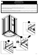
CORNER TRIM INSTALLATION INSTALLATION DE FINITION D’ANGLE INSTALACIÓN DE LA MOLDURA DE LA ESQUINA 1 1.1 Apply a silicone bead along the groove of the left wall panel. 1.2 Behind the wall panels, leaving a 1” (25mm) clearance from the top and the bottom of the wall panels, drill 9 equidistant holes using a 3/16” (5mm) drill bit to join the two walls panels. 1.1 Appliquer un cordon de silicone le long de la rainure du panneau mural gauche. 1.
WALL PANEL INSTALLATION INSTALLATION DES PANNEAUX MURAUX INSTALACIÓN DEL PANEL DE LA PARED 2 2.1 Tightly screw the wall panels together with the bolts, washers, and nuts (GG). 2.1 Visser fermement les panneaux muraux avec les boulons, rondelles et écrous (GG). 2.1 Atornille firmemente los paneles de la pared junto con los pernos, arandelas y tuercas (GG). 2.1 GG 9X Top view Vue de haut Vista de arriba SILICONE SILICONE SILICONA P.
3 WALL PANEL INSTALLATION INSTALLATION DES PANNEAUX MURAUX INSTALACIÓN DEL PANEL DE LA PARED 3.1 Firmly push the wall panels (E & F) onto the drywalls. Ensure that the wall panels are flush with the shower base edge. 3.1 Pousser fermement les panneaux muraux (E et F) sur les cloisons sèches. Assurez-vous que les panneaux muraux sont au ras du bord de la base de la douche. 3.1 Empuje firmemente los paneles de pared (E y F) sobre las paredes secas.
INSTALLATION MANUAL | MANUEL D’INSTALLATION | MANUAL DE INSTALACIÓN DO NOT START WITH THIS INSTALLATION MANUAL 1) FIRST, INSTALL YOUR SHOWER BASE. 2) SECOND, INSTALL YOUR SHOWER WALL PANELS. 3) THIRD, INSTALL YOUR SHOWER ENCLOSURE.(USING THIS MANUAL) NE PAS COMMENCER PAR CE MANUEL D’INSTALLATION 1) PREMIÈREMENT, INSTALLEZ VOTRE BASE DE DOUCHE. 2) DEUXIÈMEMENT, INSTALLEZ VOS PANNEAUX MURAUX. 3) TROISIÈMEMENT, INSTALLEZ VOTRE CABINE DE DOUCHE.
TABLE OF CONTENT TABLE DES MATIÈRES TABLA DE CONTENIDOS TABLE OF CONTENT......................................... 2 TABLE DES MATIÈRES...................................... 2 TABLA DE CONTENIDOS................................... 2 SHOWER DIMENSIONS...................................... 3 DIMENSIONS DE LA DOUCHE.......................... 3 DIMENSIONES DE LA DUCHA........................... 3 INSTALLATION STRUCTURE OVERVIEW........ 4 VUE D’ENSEMBLE DE LA STRUCTURE D’INSTALLATION ......................
SHOWER DIMENSIONS DIMENSIONS DE LA DOUCHE DIMENSIONES DE LA DUCHA Measurements Mesures 32" 34" 36" 38" O 29 13/16" 758mm 31 1/4" 793mm 33 7/16" 850mm 35 7/8" 911mm O Shower width (wall track to wall track) Largeur de la douche (glissière à glissière) Ancho de la ducha (pista de pared a pared) U 72 13/16" 1850mm 72 13/16" 1850mm 72 13/16" 1850mm 72 13/16" 1850mm U Shower height Hauteur de la douche Altura de la ducha V 22 13/16 R23" 582 R584mm 25 1/4 R23" 642 R584mm 31 9/16 R23" 801 R58
INSTALLATION STRUCTURE OVERVIEW VUE D’ENSEMBLE DE LA STRUCTURE D’INSTALLATION VISIÓN GENERAL DE LA ESTRUCTURA DE INSTALACIÓN 1. Before you start the installation of your product consult the illustration 1 below showing a side-view of the completed installation. 2. Illustration 2 shows the recommended wall structure and measurements for the product installation. NOTE: Customer must follow and comply with the local and national building and plumbing codes.
PACKAGE CONTENT CONTENU DE L’EMBALLAGE CONTENIDO DEL PAQUETE A B D C E H F G I J K L M PAGE 5
PACKAGE CONTENT CONTENU DE L’EMBALLAGE CONTENIDO DEL PAQUETE A 2x B 2x C 2x D 2x E 2x F 1x G 1x H 1x I 1x J 1x K 1x L 1x M 2x PAGE 6
PART LIST LISTE DES PIÈCES LISTA DE PIEZAS PART # # DE PIÈCE PARTE # DESCRIPTION DESCRIPTION DESCRIPCIÓN QUANTITY QUANTITÉ CANTIDAD CODE CODE CÓDIO 32” Chrome / Chrome / Cromo: 99STR1033 34” Chrome / Chrome / Cromo: 99STR1034 36” Chrome / Chrome / Cromo: 99STR1035 38” Chrome / Chrome / Cromo: 99STR1036 32” Satin Nickel / Satiné / Satinado: 99STR3766-AC A Frame track (top and bottom) Glissière du cadre (haut et bas) Corredera de marco (superior e inferior) 2 34” Satin Nickel / Satiné / Satinado: 99STR
PART LIST LISTE DES PIÈCES LISTA DE PIEZAS PART # # DE PIÈCE PARTE # DESCRIPTION DESCRIPTION DESCRIPCIÓN QUANTITY QUANTITÉ CANTIDAD CODE CODE CÓDIO 32” Chrome / Chrome / Cromo: 99SG10018-AC 34” Chrome / Chrome / Cromo: 99SG10327-AC 36” Chrome / Chrome / Cromo: 99SG10328-AC 38” Chrome / Chrome / Cromo: 99SG10329-AC 32” Satin Nickel / Satiné / Satinado: 99SG3754-AC Transparent glass Verre transparent Vidrio transparente 34” Satin Nickel / Satiné / Satinado: 99SG3755-AC 36” Satin Nickel / Satiné / Satinado
SUPPLIED HARDWARE LIST QUINCAILLERIE FOURNIE CONTENIDO DE HARDWARE AA BB CC DD Screw Vis Tornillo ST4x45 12+2 Screw Vis Tornillo ST3.
PREPARATION PRÉPARATION PREPARACIÓN This instruction is drawn up for a door opening from right to left (see illustration A). For an installation for a door opening from left to right (see illustration B), use the same instructions, but switch around the panels: mirror effect. Utilisez ces instructions pour une ouverture de la porte de droite à gauche (illustration A).
SAFETY INFORMATION INFORMATION SUR LA SÉCURITÉ INFORMACIÓN DE SEGURIDAD CAUTION Please carefully read the following important safety information before handling or installing this shower. There is a risk of serious injury while handling this product. To minimize these risks, please note: • • • • • • • • • • • • • Always wear safety glasses and gloves while handling. Always read and follow all the steps in the installation instructions. Inspect all contents and glass for damage before installation.
SAFETY NOTICE AVIS DE SÉCURITÉ AVISOS DE SEGURIDAD NOTICE Any modification or alteration from what is specified in this instruction manual will void any and all warranty on this product. The distributor is not responsible for any damage to the unit or personal property caused by improper installation. If you disregard instructional warnings, you will void your warranty and possibly deal with water damage.
FRAME INSTALLATION INSTALLATION DU CADRE INSTALACIÓN DE MARCOS 1 1.1. Insert the fixed panel seal strip (B) on top of the fixed panel (F). Screw the top left side of fixed panel (F) to the frame track (A) using screws (BB). 1.2. Screw the top right side of the door track (L) to the frame track (A) using screws (BB). 1.3. Insert the fixed panel seal strip (B) on bottom of the fixed panel (F). Screw the bottom left side of fixed panel (F) to the frame track (A) using screws (BB). 1.4.
FIXED PANEL INSTALLATION INSTALLATION DU PANNEAU FIXE INSTALACIÓN DE PANELES FIJOS 2 2.1-2.2. Secure the fixed panel (J) to the frame by using the clamps (C). Attach the clamps (C) using the screws (DD). 2.1-2.2. Visser le panneau fixe (J) au châssis à l’aide des attaches (C). Visser les attaches (C) à l’aide des vis (DD). 2.1-2.2. Fije el panel fijo (J) al marco utilizando las abrazaderas (C). Fijar las abrazaderas (C) con los tornillos (DD). 2.1 C DD L F 2.
3 FIXED PANEL INSTALLATION INSTALLATION DU PANNEAU FIXE INSTALACIÓN DE PANELES FIJOS 3.1. Insert the fixed panel seal strip (G) onto the fixed panel (F). 3.1. Insérez le joint d’étanchéité du panneau fixe (G) sur le panneau fixe (F). 3.1. Inserte la banda de sellado de panel fijo (G) en el panel fijo (F). 3.
WALL TRACK INSTALLATION INSTALLATION DE LA GLISSIERE INSTALACIÓN DEL RIEL DE PARED 4 4.1. Insert the wall tracks (E) onto the sides of the assembled frame. Do not screw in the wall track at this step. 4.1. Insérez les glissières murales (E) sur les côtés du cadre monté. Ne pas visser les glissières murales à cette étape. 4.1. Inserte las pistas de pared (E) en los lados del marco ensamblado. No atornille los rieles de pared en esta etapa. 4.
5 SHOWER FRAME INSTALLATION INSTALLATION DU CADRE DE DOUCHE INSTALACIÓN DEL MARCO DE DUCHA 5.1. Take the assembled shower frame and gently put it onto the installed shower base. Ensure that all leveled. Position the frame such as the center of the wall track will be located on the center line of the shower base, as illustrated below. 5.1. Prenez le cadre de douche monté et placez-le délicatement sur le cadre de douche installé. S’assurer que tout est à niveau.
6 SHOWER FRAME INSTALLATION INSTALLATION DU CADRE DE DOUCHE INSTALACIÓN DEL MARCO DE DUCHA 6.1-6.2. Mark the pre-drilled holes of the wall tracks (E) onto the wall, and then remove the assembled shower frame from the base. 6.1-6.2. Marquez les trous prépercés des glissières murales (E) sur le mur, puis retirez le cadre de douche assemblé de la base. 6.1-6.2. Marque los agujeros pretaladrados de las pistas de pared (E) en la pared, y luego retire el marco de ducha ensamblado de la base. 6.1 6.
SHOWER FRAME INSTALLATION INSTALLATION DU CADRE DE DOUCHE INSTALACIÓN DEL MARCO DE DUCHA 7 7.1. Using a ø1/4” (6mm) drill bit, drill guide holes at the marked location. 7.2. Insert the wall anchors (CC) using a rubber mallet until the wall anchors are flush with the wall. 7.1. À l’aide d’une mèche ø1/4” (6mm), percez des trous de guidage à l’endroit indiqué. 7.2. Insérez les ancrages muraux (CC) à l’aide d’un maillet en caoutchouc jusqu’ à ce que les ancrages muraux soient au ras du mur. 7.1.
8 SHOWER FRAME INSTALLATION INSTALLATION DU CADRE DE DOUCHE INSTALACIÓN DEL MARCO DE DUCHA 8.1. Put the assembled shower frame back onto the base. 8.1. Remettez le cadre de douche monté sur la base. 8.1. Vuelva a colocar el marco de ducha montado en la base. HELPFUL HINT! Before installing the frame, you may insert the door panel in the shower base to facilitate future steps.
9 SHOWER FRAME INSTALLATION INSTALLATION DU CADRE DE DOUCHE INSTALACIÓN DEL MARCO DE DUCHA 9.1. Secure the wall tracks (E) using the washers (GG), screws (AA), and covers (FF). 9.1. Fixez les glissières murales (E) à l’aide des vis (AA), des rondelles (GG) et des capuchons pour vis (FF). 9.1. Asegure los pistas de la pared (E) usando las arandelas (GG), los tornillos (AA) y las tapas roscadas (FF). 9.
10 SHOWER FRAME INSTALLATION INSTALLATION DU CADRE DE DOUCHE INSTALACIÓN DEL MARCO DE DUCHA 10.1. Secure the shower frame to the wall tracks (E) using washers (GG), screws (EE), and caps (FF). 10.1. Fixez le cadre de douche aux glissières murales (E) à l’aide de rondelles (GG), de vis (EE) et de Capuchon pour vis (FF). 10.1. Fije el marco de la ducha a los pistas de la pared (E) usando arandelas (GG), tornillos (EE) y tapas roscadas (FF). 10.
WHEELS INSTALLATION INSTALLATION DES ROUES INSTALACIÓN DE RUEDAS 11 11.1. Insert the door panel seal strip (H) on the left side of the door (J). 11.2. Insert the magnetic seal strip (K) on the closing end of the door (J). 11.3. Insert the top door wheels (D) into the wheel holders. 11.4. Insert the bottom door wheels (M) into the wheel holders. 11.1. Insérez le joint d’étanchéité de la porte (H) sur le côté gauche de la porte (J). 11.2.
SHOWER DOOR INSTALLATION INSTALLATION DE LA PORTE DE DOUCHE INSTALACION DE LA PUERTA DE DUCHA 12 12.1. Gently hang the door (J) by its top wheels (D). 12.2. Secure the bottom wheels into the bottom frame track (A) by pushing down on the bottom wheel. A spring action will secure the bottom wheels into the frame track. 12.1. Suspendez délicatement la porte (J) par les roues supérieures (D). 12.2. Fixez les roues inférieures dans la glissière du cadre inférieur (A) en appuyant sur la roue inférieure.
13 DOOR INSTALLATION INSTALLATION DE LA PORTE INSTALACIÓN DE PUERTAS 13.1. Ensure that the door closes well and that it is leveled. If an adjustment is needed, use a screwdriver to tighten or loosen the screw located under the top rollers to level the door adequately. 13.1. Assurez-vous que la porte se referme bien et qu’elle soit nivelée. Si un ajustement est nécessaire, serrez ou desserrez la vis située sous les rouleaux supérieurs à l’aide d’un tournevis pour ajuster correctement la porte. 13.1.
HANDLE INSTALLATION INSTALLATION DE LA POIGNÉE INSTALACIÓN DE LA MANIJA 14 14.1. Install the handle (I). 14.1. Installer la poignée (I). 14.1. Instalar el mango (I). I 14.
15 SEALING SCELLAGE SELLADO Ensure that the door closes tightly and opens smoothly. Ensure that there is a firm connection between the fixed panel(s) and the support bar. Apply a clear silicone water sealant around the outside perimeter of any fixed shower components. Allow 24 hours for silicone to dry. Improper application of silicone sealant may cause your shower to leak.
MAINTENANCE AND CARE ENTRETIEN ET MAINTENANCE MANTENIMIENTO Y CUIDADO For the daily maintenance, use a wet cloth and a soft liquid cleaner. Never use abrasive cleaners containing some acetone, chlorine or strong bleach, scrapers, metallic brushes, nor other objects or the products which can graze or tarnish surfaces. Use a ratchet to strongly tighten any bolts used to support the fixed glass panels or doors panel (support bolts can withstand up to 250 lbf*in of torque).
LIMITED Product Warranty The DISTRIBUTOR is a distributor of the following Products: • Shower Doors (warranty period 5 years). • Acrylic Surfaces (warranty period 5 years against blistering, cracking or chipping in the acrylic surface). • Acrylic Shell Structure (warranty period 5 years against loss of water through fiberglass laminate of the acrylic body).