VISUAL HEADLAMP ALIGNMENT SYSTEM ASSEMBLY OPERATION CALIBRATION 524 S.E. Transport Drive Lees Summit, MO 64081 Safety by Design 888-884-8182 816-525-9263 FAX: 816-525-9283 www.symtechcorp.
INDEX 1. GENERAL Pg. 3 1.1 1.2 1.3 1.4 “BCA 4 ISOCOLOR ” INTRODUCTION SYSTEM COMPONENTS LASER WARNING WARNING, EXPOSURE TO DIRECT SUNLIGHT 2. ASSEMBLY Pg. 4 2.1 2.2 2.3 2.4 2.5 2.6 BASE / WHEEL ATTACHMENT MAST / GLIDE PLATE / ROTATIONAL MAST MOUNT OPTICAL ALIGNMENT HEAD SIGHTING UNIT SIGHTING UNIT CALIBRATION FLOOR SLOPE LASER 3. OPERATION Pg. 6 3.1 ALIGNMENT BAY(s) PREPARATION 3.2 FLOOR SLOPE MEASUREMENT 3.3 VEHICLE PREPARATION, Prior to Alignment 4. HEADLAMP ALIGNMENT PG. 7 4.
1. GENERAL 1.1 INTRODUCTION The Model “BCA 4 ISOCOLOR” Visual Headlamp Alignment System is an economical optical alignment tool that functions under the same principle for accuracy and dependability of an aiming screen, with the added benefit of Symtech Corporation’s “BCA 4 ISOColor” technology, without the excessive use of valuable shop space and the confusion of vertical and horizontal lamp placement. System design and operation has been engineered with the technician in mind.
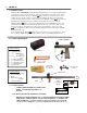
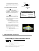
2. ASSEMBLY Inspect all components of the :BCA 4 ISOColor system to assure that no damage has occurred during shipment, compare contents of package with that of the exploded view to make sure that no component has been inadvertently left out of packaging. If a component is missing, contact our customer service department at 888-884-8182 for an immediate replacement. 2.1 BASE / WHEEL ATTACHMENT Front of Base Place base of system on floor, or table with channel facing downward.
Place a thick nylon bushing on the screw and insert screw through the holes provided at the top of the mast, place a thick nylon bushing on screw and selflocking nut. Tighten to a tension that allows for movement of sighting unit, but provides sufficient friction to hold unit in place when unattended. NOTE: Sighting unit must be calibrated to the optical head prior to alignment of headlamps. 2.5 SIGHTING UNIT CALIBRATION Calibration of sighting unit must be performed prior to alignment of headlamps.
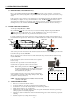
3. OPERATION PROCEDURES 3.1 PREPARATION, ALIGNMENT BAY(s) Prior to any headlamp alignment using the BCA 4 ISOColor, the floor slope of the bay, or bays must be determined, this is done by using the floor slope laser assembly and noting the position of the rear floor slope wheel. If the correct floor slope of the bay is not adjusted prior to any headlamp alignment, the technician will align the headlamps in a higher, or lower position than what is correct.
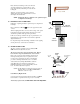
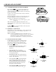
4. HEADLAMP ALIGNMENT 4.1 ALIGNMENT OF OPTICAL HEAD TO VEHICLE Place the BCA 4 ISOColor in front of the first headlamp to be aligned. Once the BCA 4 ISOColor is in place, the lens of the optical head should be approximately 12 inches (+/- 6 inches) from the face of the headlamp. Set the floor slope of the eccentric wheel for the bay in which the vehicle has been parked. Common Points Rotate the sighting unit so that the front of the vehicle can be seen through the sighting unit.
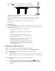
vehicles. The high intensity area is located in the lower right hand quadrant and the beam pattern is aligned by placing the left upper portion of the beam pattern on the .4 Degree (2.096”) Down Horizontal axis. H .4 Degree Down (2.096 Inches) 4.4 ALIGNMENT OF HEADLAMP PROCEDURE 1. Locate BCA 4 ISOColor approximately 12 inches from in front of the lamp to be aligned. Placement can be 6” to 18” without jeopardizing alignment. 2. Position BCA 4 ISOColor in front of first lamp to be aligned.
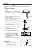
Move BCA 4 ISOColor to end of straight edge, turn on the laser and adjust height of optical head so that the mounted laser will shoot down the straight edge. Adjust the rear floor slope wheel until the level in the optical head is centered. Readjustment of height of optical block may be necessary. Adjust the rear height adjustment set screw of the laser assembly (Lock Tight has been installed on screw at factory, minor pressure should break seal) till laser is viewed at both ends of straight edge equally.
Question: I cannot attain equal readings at the front wheel and the rear wheel areas when determining the floor slope. Answer: The only time that this can occur is when the shop bay has an abnormally excessive angle of slope. The most frequent problem with determining floor slope is patience in adjusting until the measurements are equal. A TRICK to assist in making this measurement is to first measure the height of the laser at the optical head.